Download
1 / 14
140 likes | 152 Views
Manifolds optimization and pressure drops in the ATLAS TRT CO 2 cooling system. Joël Grognuz. Holes for p static measurements. Manifold experiment.

E N D
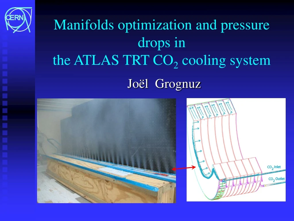
Manifolds optimization and pressure drops inthe ATLAS TRT CO2 cooling system Joël Grognuz
Holes for pstatic measurements Manifold experiment • Full scale straight half manifold (2m, 40 holes for inlet, 3m, 48 holes for outlet) manufactured from aluminum U profiles with plexiglas glued on top. • For fixed Qin/out, measure pnozzle(z), and qnozzle(z) Outlet manifold mock-up Water U manometers Wisag flow-meterfor Qout ez Pump 48 holes under the rail Manifolds optimization, Joël Grognuz
Manifold experiment Inlet first results: • Flux variation of 40 % • qnozzle measurements are good for pnozzle> 12mbar: • qnozzle(z) may: • be increasing • have a local minimum • be decreasing Increasing ! depending on holes sizes, Qin and friction losses. Manifolds optimization, Joël Grognuz
Outlet manifold Model • Nozzle flow resistance coefficient: • depends on the geometry of the flow at the nozzle: for inlet manifolds, the resistance increases with the flow perpendicular to the nozzle, whereas the opposite happens for outlet manifolds! Inlet manifold Manifolds optimization, Joël Grognuz
Model validation (air) • Outlet ( calibrated from 2 mm diameters, Q_{in}= 25 m3h-1) • Inlet ( calibrated from 3.7 mm diameters, Q_{in}=37.5 m3h-1) q variation = 11% Manifolds optimization, Joël Grognuz
Dimensioning of TRT manifolds Poiseuille flow (laminar) • Characteristics: • qnozzle(z) unlike pnozzle(z) fairly constant with varying Qin/out or . • Changes in model for CO2: • density: • kinematic viscosity: • D’Arcy friction factor (from chart for laminar and turbulent flows): • Flow resistance coefficient with zero perpendicular flux: • Manifold cross-section: 52 x 6.35 or 42 x 7 42 x 7.35 mm special setup to measure 0: Manifolds optimization, Joël Grognuz
Optimized holes distributions (CO2) • Inlet (qnozzle variation = 12%) • Outlet (qnozzle variation = 24%) Manifolds optimization, Joël Grognuz
Pressure drops in system (best case) Manifolds optimization, Joël Grognuz
Pressure in system (best case) Manifolds optimization, Joël Grognuz
Pressure drops in system (worst case) Manifolds optimization, Joël Grognuz
Pressure in system (worst case) Manifolds optimization, Joël Grognuz
CO2 system simulation result TRT pressure oscillations increase with valve response-time and flow/pressure: (qualitative results) Manifolds optimization, Joël Grognuz
TRT wheels passive protection • Safety valve: • Valves work for p>10mbar • Placing valves upstream and downstream is not totally safe! • Rupture disc: • Space limitation problem • Accessibility if need to be changed!? 5cm Manifolds optimization, Joël Grognuz
Further work • Resurrect the cooling system simulation • Define and order components (C-wheel!?, pipe routes) • Passive safety device on wheels!? • Find a location to build prototype #2 • Build it! Manifolds optimization, Joël Grognuz