Download
1 / 9
90 likes | 160 Views
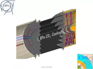
Physics Department. D etector T echnology Group. Pixel CO 2 Cooling Tests. B187 CO 2 Test Setup. CO2 Blow-system Process Path. C. A. B. D. B. A. Pressure [Bar]. E. F. C. D. F. E. Enthalpy [kJ/kg]. BPix Cooling Tube Testing. BPix Cooling Layout :.

E N D
Physics Department Detector Technology Group Pixel CO2 Cooling Tests
B187 CO2Test Setup CO2 Blow-systemProcessPath C A B D B A Pressure [Bar] E F C D F E Enthalpy [kJ/kg] JoãoNoite
BPixCoolingTubeTesting BPixCoolingLayout: Experimental vs Theorectical: BPixLayer #1 L=5.5m ID=1.4mm T=-20°C P=150W João Noite
BPixMock-upTesting • SS 1.4 mm ID coolingtube. • 5.5 m total tubelength. • 9x 180°tubebends, 7mm radius. • 8x 54x18 mm SS heatingplates. • Powerfrom 50 to 200 W. • CO2 temperature -20°C and -30°C. • CO2 massflowfrom 1 to 1.5g/s. S3 S1 S7 S9 S5 S8 S2 S4 S6 P3 P2 P1 P6 P5 P4 S10 P7 P9 P8 P11 P12 P10 João Noite
FPixCoolingTubeTesting FPixCoolingStructure: Experimental vs Theorectical: FPixTubeL=1m ID=1.4mm Pmax=124W T=-30 to 9°C João Noite
BPixCarbonFiberSupportStructure – T300J vs K1100 ANSYS Calculation T300J: • BPix¼Module: • SS Tube OD=1.6mm • ROC Simulated Power=3W • SupportStructure Material: • - CarbonFiber T300J, k=10W/m.K • - CarbonFiber K1100, k=500W/m.K • Glue: Epoxy, k=0.35W/mK • Mainobservations: • K1100 - ΔT=1.35°C • T300J – ΔT=10.4°C ANSYS Calculation K1100: João Noite
ThermalContactTest Experimental Models: SimulationModels: João Noite
ThermalContact - ANSYS Calculations • ThermalContactModel 1: • SS Tube OD=1.6mm • Pmax=3W→2778W/m2 • Epoxy: k=0.35W/m.K • Copper: k=400W/m.K • CarbonFiber: k=10W/m.K • Mainobservations: • Power=3W - ΔT=13.7°C • ThermalContactModel 2: • SS Tube OD=1.6mm • Pmax=3W→2778W/m2 • Conductive Paste: k=0.35W/mK • Mainobservations: • Power=3W - ΔT=3.7°C João Noite
Conclusions • Software of some correlations are now fully debugged an operational. • Interesting differences between calculations and measurements remain. • FPIX tube can reliably cool the requested heat load of 124 W. • ΔT over tube length < 3°C • ΔT due to HTC < 3°C • CalculationsoftheBPixstructure show thatthe use ofhighconductivefibersgivesmuchbetter performance, ΔT<2°C. • Designingthethermal interface betweenthetubeandthecarbonstructurestillrequiresmuchwork. João Noite