Download
1 / 46
530 likes | 959 Views
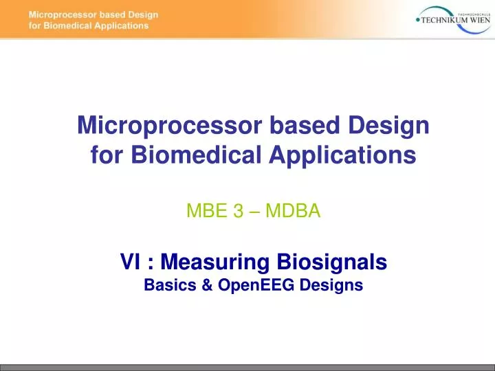
Microprocessor based Design for Biomedical Applications MBE 3 – MDBA VI : Measuring Biosignals Basics & OpenEEG Designs. Last lecture: Origin and characteristics of bioelectric signals Electrodes and sensors Review of Project exercises Programming. Today: Electrode-Skin interface

E N D
Microprocessor based Design for Biomedical ApplicationsMBE 3 – MDBAVI : Measuring BiosignalsBasics & OpenEEG Designs
Last lecture: Origin and characteristics of bioelectric signals Electrodes and sensors Review of Project exercises Programming
Today: Electrode-Skin interface Opamps and Instrumentation Amplifiers Challenges for a good EEG recording EagleCad and LTSpice The ModularEEG Design The MonolithEEG Design
Electrode – Skin Interface: M+ : metallic Cathions A- : organic Anions
Electrode – Skin Interface: ● Electorde-polarization can reach several hundert millivolts ●Non-polarizable electrodes: chlorided silver Ag/AgCl
Chloriding a silver electrode: ● Apply current for approximately 1 minute. ●The chloriding electrode darkens, while the other bubbles
Capacitive coupling, body model: ● unbalanced electrode impedances turn common mode voltage into difference mode voltage
Impedance monitoring: http://www.brainmaster.com/productinfo/accessoryequip/checktrode3.jpg http://www.general-devices.com/pcheck1.jpg
Low cost impedance checker: ●MP3 player or Laptop SoundCard as AC source ●Voltage divider effect: mesaure AC with multimeter at TP1/2 ●Vout > ½ Vin Use a battery powered Mp3 player or laptop for Safety reasons ! by Ian McCulloch, http://flickr.com/photos/ianmc333/458904528
Sources of Interference and Noise: ● Capacitive coupling of noise / line-hum (common mode voltages) ● Inductive coupling of AC-sources ●Artefacts due to other (stronger) biosignals ● Movement-Artefacts ●High electrode impedances ● unbalanced electrode impedances ●Electrode - Polarization ●internal (thermal) noise of the components
Strategies to handle noise / interferences ● increase distance to electriceal devices and cables ● use shielding (Faraday - Cage) ● decrease Electrode impedance (contact gel, skin cleaning) ● avoid ground loops ● use a 50/60Hz notch filter ● cable shiedling and driven shields (guarding). ●use a driven right leg circuit / closed loop system to increase common mode rejection Ad … Differential gain Ucm … Common mode voltage at the inputs Ua … voltage at the output
Instrumentation Amplifier ● high input impedance ~ 1GOhm ● low output impedance ● high common mode rejection CMRR ~ 110 dB ● adjustable gain (Rg) Capacitive coupling of Common Mode voltages into cables ~ 100 mV ! -> Instrumentation Amplifier measures voltage difference
Measurement Chain, Aliasing Source Amplification Filtering A/D-Conversion Digital Value correct fsample insufficient fsample
Measurement Chain Source Amplification Filtering A/D-Conversion Digital Value
Nyquist Frequency, Anti-Aliasing Filter ● fsignal < fNyquist ( fNyquist = ½ fsample ) -> band-limit the Input Signal using a Low Pass Filter ● Sallen Key (lowpass configuration): cutoff fc = 1 / (2π*R*C) gain G = 1+Rf/R1 OpAmp slew-rate has to match frequency range active Low Pass Filter (Sallen Key Circuit)
Active Filter designer software (TI) http://focus.ti.com/lit/sw/slvc003d/slvc003d.zip
WaveRider Pro Channels: 5 (1 GSR) Resolution: 8 bit 1 LSB: 0,17 uV CMMR: 100 dB Filtering: 50Hz Notch 0,5 Hz Highpass40 Hz Lowpass (-70 dB /50Hz) Sampling Rate: 255 Hz Interface: serial (Rs232) Power Supply: 9 V – batteryMed. certified: no Price: $ 1.500 Company: Mindpeak, http://mindpeak.com
SYMTOP EEG-Amplifier Channels: 16-41 Resolution: 16 bit 1 LSB: 0,5 uV CMMR: 98 dB Noise: < 2,5uVpp Filtering: Highpass 1 / 3 /10 Hz Lowpass 15 /30/45/60/120Sampling Rate: 1 kHz Interface: serial (USB) Power Supply: mains adapterMed. certified: yes Price: $ 4.000 Company: http://www.symtop.com
g.tec USBamp Channels: 16 Resolution: 24 bit 1 LSB: 30 nV CMMR: 98 dB Noise: < 0,3 uVpp Filtering: Highpass generic Lowpass genericSampling Rate: 38,4 kHz Interface: serial (USB) Power Supply: mains adapterMed. certified: yes Price: $ 10.100 Company: http://www.gtec.at
Neuroscan Synamp2 EEG Verstärker Channels: 64 Resolution: 24 bit 1 LSB: 3 nV CMMR: 108 dB Noise: < 0,4 uVpp Filtering: Highpass DC/0,5Hz Lowpass 3.500 HzSampling Rate: 20,4 kHz Interface: serial (USB) Power Supply: mains adapterMed. certified: yes Price: $ 32.000 (48.000 inc. Software) Company: http://www.neuro.at
ModularEEG ● first design of the OpenEEG project ● Author: Joerg Hansmann ●one digital board, up to three analog boards -> 2 to 6 channels ●http://openeeg.sf.net
ModularEEG Channels: 2 - 6 Resolution: 10 bit 1 LSB: 0.5 uV Sampling rate: 256 Hz (up to 1 kHz depending on optocouplers) Noise: 1 uVpp Current Consumtion: 70 mA (2 channels) Isolation : 2.500V (1 minute), 480V (continuous) Med. certified: no Operating voltage: 9 - 15 V (battery or mains adapter)
ModularEEG analog board block diagram (1 channel) ● User / ESD protection ●Signal conditioning: amplification + HP / LP filtering ● DRL: closed control loop to cancel CM
ModularEEG digital board block diagram ● Power supply regulation, DC/DC-conversion, LP-filter ● Reference Voltage: 4V, Virtual ground: 2V ●uC: Sampling and data protocol, UART ● Isolated data transfer: MAX232, optocoupler
ModularEEG analog stages schematics – protection circuit ● C204, 205,209 suppress RF-signals ● Q201, 203, 205, 207 + R201, 202, 205-208 limit current transistors are used as clamping diodes -> V < 0,7 Volts
ModularEEG analog stages schematics - first gain stage ● INA114 Instrumentation Amp. ● suitable supply range: +/-2,25V ●low drift and offset voltage ●low noise for given source impedances: 0.4uVpp (.1-10Hz) ● Gain 1 to 10000 1 + (50kOhm / ( R214+R215)) set to 12.2 ● Comon mode voltage measured between R214 and R215 and passed to DRL circuit DRL
DRL: Driven Right Leg circuit ● negative Feedback loop ● output to the body ● improves CMRR by cancelling out CM
ModularEEG analog stages schematics - DRL circuit ● DRL-implementation using inverting amplifier and integrator circuit ● further reading: http://www.biosemi.com/publications.htm
ModularEEG analog stages schematics - filter / gain stages HP 1pole 0.16Hz ● first high-pass 0.16 Hz ● Non-inverting amplifier G = (Ra+Rb) / Ra (Ra=1k + P202 Rb=100k) ● second high-pass 0.16 Hz ● active 2nd order low-pass 59Hz, gain=16 ● 3rd pole located at digital board, near ADC input pin
ModularEEG Bode Plot: single and combined stages
MonolithEEG: ● based upon the Modular EEG ● Author: Reiner Münch ●2 channels, one double-sided SMD board ● USB data transfer and USB powered ● improved noise characteristics ●http://freenet-homepage.de/moosec/projekte/simpleeeg
ModularEEG -> MonolithEEG – design changes LP 1pole 48Hz ● Instrumentation Amplifier changed to INA118 ● Active working point stabilisation, removes DC-voltage (->active highpass) ● pre LP-filter for the active sallen key lowpass
ModularEEG ->MonolithEEG – design changes ●changed values of filter components: slightly improved operating range and higher slew rate
MonolithEEG – microcontroller digital section ● ATmega8 uC ● decoupled analog reference voltage ● 3rd pole of lowpass filter near analog inputs ● SPI interface and GPIO pins routed to expansion port
MonolithEEG – USB-interface ● FTDI driver delivers VCP Port ● 5v supply from USB port ● suspend circuit added in current design version
MonolithEEG – power supply / stabilization ●similar to the ModularEEG, except 5V from USB ●Power supply filtering: removing switching noise, double filtered analog supply
MonolithEEG – power rails / VGND ● generate stabilized 4V : TL431 shunt regulator (2.5V ref.) : ●buffered 2V virtual Ground for split-rail supply
Returning to the digital domain: The OpenEEG P2 Packet Formats
The OpenEEG P2 Packet Format Byte 1: Sync Value 0xa5 Byte 2: Sync Value 0x5a Byte 3: Version Byte 4: Frame Number Byte 5: Channel 1 Low Byte Byte 6: Channel 1 High Byte Byte 7: Channel 2 Low Byte Byte 8: Channel 2 High Byte Byte 9: Channel 3 Low Byte Byte 10: Channel 3 High Byte Byte 11: Channel 4 Low Byte Byte 12: Channel 4 High Byte Byte 13: Channel 5 Low Byte Byte 14: Channel 5 High Byte Byte 15: Channel 6 Low Byte Byte 16: Channel 6 High Byte Byte 17: Button States (b1-b4) ● first transmission protocol ● easy to generate / parse ● not optimized for speed
The OpenEEG P3 Packet Format Byte 1:0ppppppx packet header Byte 2:0xxxxxxx Byte 3:0aaaaaaa channel 0 LSB Byte 4:0bbbbbbb channel 1 LSB Byte 5:0aaa-bbb channel 0 and 1 MSB Byte 6:0ccccccc channel 2 LSB Byte 7:0ddddddd channel 3 LSB Byte 8:0ccc-ddd channel 2 and 3 MSB Byte 9:0eeeeeee channel 4 LSB Byte 10:0fffffff channel 5 LSB Byte 11:1eee-fff channel 4 and 5 MSB 1 and 0 = sync bits. p = 6-bit packet counter x = auxilary channel byte a-f = 10-bit samples chn. 0 - 5 - = unused, must be zero ● optimized for speed / memory usage
other Packet Formats ● P21 by Jarek Foltynski: bidirectional transmission support ● P21_v2 by Reiner Münch: new commands supported by BrainBay host software