Download
1 / 84
850 likes | 1.36k Views
Multi-Projector Displays using Camera-based Registration. Ramesh Raskar, Michael S. Brown, Ruigang Yang, Wei-Chao Chen, Greg Welch, Herman Towles, Brent Seales, Henry Fuchs University of North Carolina at Chapel Hill. Multi-Projector Panoramic Displays. Traditional Display Setups.

E N D
Multi-Projector Displays usingCamera-based Registration Ramesh Raskar, Michael S. Brown, Ruigang Yang, Wei-Chao Chen, Greg Welch, Herman Towles, Brent Seales, Henry Fuchs University of North Carolina at Chapel Hill
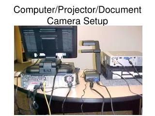
Multi-Projector Panoramic Displays Traditional Display Setups
Multi-Projector Panoramic Displays Traditional Display SetupsPrecise Geometry, Well-defined overlaps
Generalized Panoramic Display Flexible Display SetupsCasually aligned projectors and screens
Traditionally rigid design Painstaking construction Room must be modified Projector alignment is tedious High maintenance cost Constant adjustments Projectors become “unaligned” over time Problem :
Generalized display environment Setup display surface approximately Align projectors casually Render with what you have Problem : Instant Panoramic Display
Seamless imagery Immersive 3D images, moving user Casually setup projectors and surfaces Low maintenance Auto-Calibration Perceptually single logical projector Multi-Projector Goal
(a) Projector Registration Geometric alignment (b) Intensity blending Smooth transition Goal : Seamless Display Projection 2 Projection 1
(a) Projector Registration Geometric alignment (b) Intensity blending Smooth transition Goal : Seamless Display
(a) Projector Registration Geometric alignment (b) Intensity blending Smooth transition Goal : Seamless Display
Goal : Seamless Display (a) Projector Registration • Geometric alignment (b) Intensity blending • Smooth transition
(a) Projector Registration Geometric alignment (b) Intensity blending Smooth transition Goal : Seamless Display
Sweet spot Static user Moving User Head-tracked user Previous approachesMulti-projector setups
Multiple projectors (well-defined overlaps) Flight sims, Panoram, Trimensions [Raskar98] Single wide-field-of-view projector OmniMax Alternate Realities Previous approaches: Sweet spot (static user) User
CAVE Rigid setup Well-defined geometry Large support structure Previous approaches:Moving user Projector User
Office of the Future [Raskar98] Relaxed construction constraints Assumes precise display geometry recovery Demonstrated for a single projector Previous approaches:Moving user
QuickTime VR Pair-wise mosaicing of photographs Generalized mosaicing Related work:Image Mosaicing
Seamless image Immersive 3D images, moving user Arbitrary projectors and surfaces Eliminate maintenance Self-calibration Perceptually single logical projector Goal for this paper
Position projectors approximately Use video cameras to recover display geometry projector configuration Track user Render images of 3D scenes Warp and blend projected images to achieve registration Basic Approach: Panoramic Display
Single projector Calibration, Display recovery, Rendering Multiple projector Registration, Blending New techniques Post rendering warp, mesh unification Outline
Single projector Rendering, Calibration, Display recovery Multiple projector Registration, Blending New techniques Post rendering warp, mesh unification Outline
(2) Render Model (1) Desired Image 2-pass Rendering 3D Display Surface Model Projector User
2-pass Rendering Project this “warped” image, the viewer will see it correctly 3D Display Surface Projector (2) Render Model (1) Desired Image User
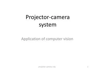
Arbitrary display surface Arbitrary projector location Need to determine these for 2 pass rendering Display Surface ? Stereo camera pair Projector ? Single projector display2-pass unknowns -How? User
Display Surface? Projector ? Single projector displayCamera calibration 1. Calibrate stereo pair Stereo camera pair
Display Surface? Projector ? Single projector displayDisplay surface estimation 1. Calibrate stereo pair 2. Determine display surface Stereo camera pair
Display Surface Projector ? Single projector displayProjector estimation 1. Calibrate stereo pair 2. Determine display surface 3. Determine projector Stereo camera pair
Single projector displayProjector estimation 1. Calibrate stereo pair 2. Determine display surface 3. Determine projector Display Surface Stereo camera pair Projector
Display surface is recovered by cameras (via projector) Surface mesh is created from the 3D points Allows us to calibrate the projector Approximate speed 720 surface point samples (~1 minute) 14,000 surfaces point samples (~15 minutes) Single projector display Display Surface Estimation
Display surface and projector are in the coordinate frame of the “Calibration Pattern” x y z Single projector displayCoordinate Frame
A single stereo-pair cannot see entire display Must use several stereo-pairs Each in its own coordinate frame Must register data into common coordinate frame Advantage We control the light Makes registration easier Multiple ProjectorsPanoramic display environments
Multiple ProjectorsSurface mesh registration Display Surface
x x x y y y z z z Multiple ProjectorsDisplay surfaces are in different coordinate frames 3 Display Surfaces 2 1
x x x y y y z z z Multiple ProjectorsMust register into common coordinate frame 3 Display Surfaces 2 1
x y z Multiple ProjectorsSurface meshes are registered into the same coordinate frame 3 Display Surfaces 2 1
x y z Multiple ProjectorsRe-calibrate projectors so they are registered 3 Display Surfaces 2 Re-calibrate the projectors so they are registered into a common coordinate frame 1
x y z Multiple ProjectorsRe-calibrate projectors so they are registered 3 Display Surfaces 2 With display surfaces and projectors registered we can achieve geometric correctness . . . 1
Multiple ProjectorsIntensity Blending Need to attenuate intensities in the overlapped region
Intensity BlendingUse camera to find overlaps Camera observes overlapped region
Intensity BlendingAssigning intensity weights (alpha) Camera image plane Assign intensity weights based on distance between projector boundaries
Intensity BlendingAssigning intensity weights (alpha) Camera image plane Assign intensity weights based on distance between projector boundaries
2 1 3 3 1 2 Intensity Blending:Alpha-masks Projector alpha-masks
Display surface and projector registration Geometrically alignment imagery Intensity blending Smooth intensity transition between projectors Achieving our goal Seamless display
Errors in estimation user location 3D display surface projector parameters Registration Issues
Errors in estimation user location 3D display surface projector parameters Single projector, errors not visible Multi-projector overlap Geometric mis-registrations Gaps, Discontinuities Registration Issues
Head-tracker for user location Display surface recovery Camera Calibration Radial Distortion Pattern Imperfection Feature detection Projector calibration Relies on display surface recovery Sources of errors
Re-projection error M Projector framebuffer m' m m' m P’ P P
Minimization residual Projector not pin-hole device Inaccuracies in estimated 3D pts on display surface Sources of re-projection error
User location Display surface meshes difficult to register incorrect surface representation Projector parameters re-projection error incorrect projection matrix Effect of errors