Download
1 / 59
610 likes | 843 Views
2005 AFOSR Program Review for Sensing, Imaging and Object Recognition , Raleigh, NC, May 26, 2005. Sensing and Communications Using Ultrawideband Random Noise Waveforms. Professor Ram M. Narayanan Department of Electrical Engineering The Pennsylvania State University

E N D
2005 AFOSR Program Review for Sensing, Imaging and Object Recognition, Raleigh, NC, May 26, 2005 Sensing and Communications Using Ultrawideband Random Noise Waveforms Professor Ram M. Narayanan Department of Electrical Engineering The Pennsylvania State University University Park, PA 16802, USA Tel: (814) 863-2602 Email: ram@ee.psu.edu
Outline • Introduction • Why use noise waveforms • Noise waveform modeling • Heterodyne correlation approach • Polarimetric radar applications • Radar imaging applications • Covert communications applications • MIMO network concept • Conclusions 2005 AFOSR S&S Program Review
Introduction • Military operations require low probability of intercept (LPI), low probability of exploitation (LPE), low probability of detection (LPD), and anti-jam characteristics • Traditional radar and communications systems use conventional deterministic waveforms • Deterministic waveforms (such as impulse/short-pulse and linear/stepped frequency modulated) do not possess above desirable features 2005 AFOSR S&S Program Review
Why use noise waveforms? • Noise waveforms are inexpensive to generate both in analog and digital formats • Noise waveforms have featureless LPI/LPD characteristics and are therefore covert • Noise waveforms are inherently anti-jam and interference resistant • Noise sources are easily obtained using current microwave and RF circuit technology • Noise waveform spectral characteristics can be adaptively shaped to suit the dynamic environment • Noise waveforms are spectrally very efficient and can share spectral bands without mutual interference • Noise waveforms exhibit excellent waveform diversity characteristics 2005 AFOSR S&S Program Review
Waveform comparison 2005 AFOSR S&S Program Review
Simple noise radar architecture using homodyne correlator 2005 AFOSR S&S Program Review
Phase coherence injection • Homodyne correlation noise radar downconverts directly to DC and hence loses important phase information of returned signal • There is a way to inject phase coherence in noise radar using time-delayed and frequency-offset transmit replica • Heterodyne correlation noise radar downconverts to offset frequency and preserves phase information of returned signal 2005 AFOSR S&S Program Review
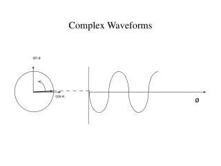
Noise waveform - stochastic model • Thermal noise is stochastic and can therefore only be described by its statistics • Noise signal x(t) can described as follows: • PDF px(X)► Zero-mean Gaussian • Autocorrelation Rxx(τ)►Impulse at τ = 0 • PSD Sxx(f)►White, assumed uniform and bandlimited • Above representation does not permit time-frequency equivalence for tracing the signal through the system 2005 AFOSR S&S Program Review
Noise waveform – time-frequency model • where • a(t) is Rayleigh distributed amplitude that describes amplitude fluctuations • δω(t) is uniformly distributed frequency that describes frequency fluctuations [-Δω≤δω≤+Δω] • average power = ½‹a2(t)›/R0, assuming a(t) and δω(t) are uncorrelated • center frequency=ω0/2π= f0 • bandwidth = 2Δω/2π= B 2005 AFOSR S&S Program Review
Bandwidth descriptors • Narrowband ► B/f0 ≤ 10% • Ultrawideband (UWB) ► B/f0 ≥ 25% Although time-frequency representation is inherently narrowband, we extend it to the UWB case owing to its simplicity and ease of signal analysis 2005 AFOSR S&S Program Review
Alternate time-frequency representation where sI(t) and sQ(t) are zero-mean Gaussian processes and f0 is the center frequency This can be recast as where Uniformly distributed Rayleigh distributed 2005 AFOSR S&S Program Review
Noise Source Power Divider Antenna Time Delay Output Mixer Antenna Homodyne correlation noise radar 2005 AFOSR S&S Program Review
Noise Source Power Divider Antenna Time Delay Offset Frequency Source LSB Upconverter Antenna Output Mixer Heterodyne correlator noise radar 2005 AFOSR S&S Program Review
Heterodyne correlation noise radar signal analysis • Transmit waveform ► • Received waveform► • Time-delayed transmit replica► • Time-delayed and frequency-offset transmit replica► • Low-pass filtered correlator output when both delays match (zero otherwise)► where Γ and Θ are magnitude and phase of target reflectivity, t0andtdare target and internal delays, and ω′is the offset frequency 2005 AFOSR S&S Program Review
Coherent reflectivity extraction • Output of correlator isALWAYSat offset frequency!! • UWB transmit waveform collapses to a single frequency! • We can shrink detection bandwidth at correlator output to enhance SNR • Power in correlator output is proportional to Γ2 • I/Q detector in receiver can measure Θ • Doppler, if any, will modulate correlator output and can be extracted from the I/Q detector • Offset frequency usually lies between 10-15% of center frequency of transmission 2005 AFOSR S&S Program Review
What can coherency give us? • Polarimetry • Interferometry • Doppler estimation • SAR imaging • ISAR imaging • Monopulse tracking • Clutter rejection ALL USING INCOHERENT NOISE RADAR!!! 2005 AFOSR S&S Program Review
Difficulty of stochastic representation 2005 AFOSR S&S Program Review
Dual-channel polarimetric noise radar architecture 2005 AFOSR S&S Program Review
Bandlimited noise waveform Frequency domain Time domain 2005 AFOSR S&S Program Review
Measured point spread functions of Channel 1 and Channel 2 2005 AFOSR S&S Program Review
Approximate resolutions • Range resolution where cis speed of light and B is the transmit bandwidth • Doppler resolution where Tint is the integration time 2005 AFOSR S&S Program Review
Average ambiguity functions B = 1 GHz Tint = 50 (L), 10 (R) ms B = 100 MHz Tint = 50 (L), 10 (R) ms 2005 AFOSR S&S Program Review
Application examples • Ground penetration imaging • Arc-SAR imaging • Polarimetric ISAR imaging • Foliage penetration (FOPEN) SAR imaging • Anti-jamming imaging performance 2005 AFOSR S&S Program Review
Ground penetration imaging Detection of multiple objects: Two metallic plates, 17.8 cm and 43.2 cm depth 2005 AFOSR S&S Program Review
Ground penetration imaging Detection of non-metallic object: Distilled water in 1 gallon plastic container, depth 7.6 cm 2005 AFOSR S&S Program Review
Ground penetration imaging Detection of polarization-sensitive object: Metallic pipe, parallel to transmit polarization and parallel to scan direction 2005 AFOSR S&S Program Review
Ground penetrating imaging Detection of polarization-sensitive object:Metallic pipe, parallel to transmit polarization and perpendicular to scan direction 2005 AFOSR S&S Program Review
Arc-SAR imaging SAR image of two corner reflectors using a 1-2 GHz random noise radar 2005 AFOSR S&S Program Review
Polarimetric ISAR imaging Geometry of mock airplane RGB color composite image of mock airplane (Red=HH, Green=HV/VH, Blue=VV) 2005 AFOSR S&S Program Review
FOPEN SAR imaging Tree-4 Tree-3 Tree-2 Tree-3 Tree-1 Tree-4 Tree-2 Trihedral-2 Trihedral-2 Trihedral-1 Trihedral-1 Tree-1 Target scenario FOPEN SAR image SVA enhanced image Images of two trihedral reflectors under foliage coverage, HH polarization 2005 AFOSR S&S Program Review
Anti-jamming imaging performance Simulated ISAR images of a MIG-25 airplane: no jamming (top), LFM radar image with SJR = -10 dB (top right), and noise radar image with SJR = -10 dB (right) 2005 AFOSR S&S Program Review
Noise Source Power Divider Channel 1 Output De- Modulator Mixer Modulator Channel 2 LSB Mixer Message Signal Transmitter Receiver Covert communications conceptual architecture Channel 1 is the “key” 2005 AFOSR S&S Program Review
Diversity implementations • Polarization diversity: Channels 1 and 2 transmitted over orthogonal polariztions • Band stacking (Frequency diversity): Channels 1 and 2 are made to occupy contiguous spectral bands • Delay diversity (Time diversity): Channel 2 delayed and transmitted after Channel 1 2005 AFOSR S&S Program Review
Diversity implementation features 2005 AFOSR S&S Program Review
Polarization diversityTransmit waveforms • Noise source output ► • Horizontally transmitted waveform► ► Noise • Modulator output ► • LSB mixer output► • Vertically transmitted waveform► ► Noise-like where ω0, ωc, ωmare the center frequency, modulator carrier frequency, and the modulating frequency respectively • If , then H and V transmit signals occupy same frequency band! 2005 AFOSR S&S Program Review
Polarization diversityReceive waveforms • Horizontally received signal ► • Vertically received signal ► • Amplitude limited horizontally received signal ► • Amplitude limited vertically received signal ► • Mixer difference output ► ► Spectrum lies between 0 and 2δω • Mixer sum output ► ► Spectrum isALWAYScentered around ωc !!! 2005 AFOSR S&S Program Review
Noise like signal White Gaussian noise Noise and noise-like signal comparison Time (s) Frequency (Hz) 2005 AFOSR S&S Program Review
Amplitude and polarization angle of transmitted signal 2005 AFOSR S&S Program Review
Instantaneous polarization vector Temporal variation of electric field vector of the propagating composite wave 1 4 2 5 6 3 2005 AFOSR S&S Program Review
BER performance without coding 2005 AFOSR S&S Program Review
BER performance with coding 2005 AFOSR S&S Program Review
Attenuation Phase Shift (delay) Channel propagation issues Four factors that may cause distortion: Atmospheric Absorption Path Loss (distance) Rain Vegetation Received Signal TransmittedSignal 2005 AFOSR S&S Program Review
Spectral efficiency issues • Since independently generated noise waveforms are uncorrelated, they can share same spectral space • Non-interference feature is useful in MIMO-type polarimetric applications to avoid cross-polarization contamination • In MIMO-type radar networking applications, many more users can be added when using noise waveforms compared to conventional waveforms 2005 AFOSR S&S Program Review
Noise waveform based networking scheme • Ultrawideband (UWB) noise used for attaining spread spectrum characteristics • UWB noise radar is used for high-resolution covert target detection, tracking, and imaging • Fragmented slices within noise band can be used for network communications (node to node and node to base station) • Camouflaged communications appears “noise like” to adversary 2005 AFOSR S&S Program Review
Waterfilling waveform optimization • Waterfilling optimization maximizes mutual information between input and output • MIMO noise radar has many options available for optimization • Waterfilling options in radar include polarization, operating frequency range, transmit bandwidth (resolution), spectral shaping 2005 AFOSR S&S Program Review
Waterfilling examples in radar • FOPEN applications: Higher signal losses through foliage for vertical polarization (due to vertically oriented trees) may imply the need for diverting larger fraction of transmit power to horizontal polarization • Imaging applications: Higher bandwidth can be used to achieve better resolution from aspect locations where higher resolution is necessary to image finer identifying features of the target, while lower bandwidth (thus better spectrum usage) may be used from aspect locations where finer features may be concealed in the shadow region 2005 AFOSR S&S Program Review
Adaptive beamforming • Adaptive beamforming has been suggested for sensor networks • Individual nodes respond to commands from base station and coordinate their transmissions to accomplish coherent beamforming • MIMO radar can greatly benefit from this approach 2005 AFOSR S&S Program Review
Adaptive beamforming examples in noise radar • Noise radar nodes can receive “pings” from base station through the covert spectrally fragmented bands • Standard approach would be an incoherent beamforming scheme since different noise waveforms are uncorrelated and phase synchronization is not possible • Incoherent beamforming may only improve received power advantage by a factor of N instead of N2 • Possible to achieve coherent beamforming if pseudorandom noise waveform is used at each node 2005 AFOSR S&S Program Review
Radar tags • Radar tag is a wireless device that can embed information into radar data acquisition by receiving radar pulses, modifying and coding these, and retransmitting them back to the radar • Backscatter modulation is primarily used in sensor networks to interrogate remote devices 2005 AFOSR S&S Program Review
Applications of radar tags in noise radar • Simultaneous “tagging” by each noise radar will not cross-pollinate other noise radars due to uncorrelated nature of the transmissions • Radar tag can be designed with specific frequency dependence to be adaptive to environment conditions as viewed by each node • Radar tags can also be used to covertly communicate information about target from one radar node to another 2005 AFOSR S&S Program Review