Download
1 / 24
250 likes | 400 Views
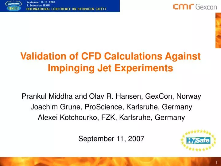
Validation of CFD Calculations Against Impinging Jet Experiments. Prankul Middha and Olav R. Hansen, GexCon, Norway Joachim Grune, ProScience, Karlsruhe, Germany Alexei Kotchourko, FZK, Karlsruhe, Germany September 11, 2007. Motivation.

E N D
Validation of CFD Calculations Against Impinging Jet Experiments Prankul Middha and Olav R. Hansen, GexCon, Norway Joachim Grune, ProScience, Karlsruhe, Germany Alexei Kotchourko, FZK, Karlsruhe, Germany September 11, 2007
Motivation • CFD calculations increasingly used for quantitative risk assessments • Validation of tool primary requirement • Important to focus on “realistic” scenarios while carrying out validation of CFD tool • Need to reproduce the complex physics of the accident scenario • Validation of tools for combined release and ignition scenarios • Recent experiments performed at FZK present an opportunity to perform “real” validation against a complex experiment • Possibility to develop risk assessment methods for hydrogen applications • (Caution: Not large scale)
Experimental Details (1) • Release of hydrogen in a ”workshop” setting followed by ignition • Nine different release scenarios • Total hydrogen inventory fixed (10 g)
Experimental Details (2) • Two different geometrical configurations • Released H2 ignited using at two different ignition positions (0.8 and 1.2 m above the release nozzle) Plate Geometry Hood Geometry
CFD Tool FLACS (1) • Solution of 3D compressible Navier-Stokes equations using a finite volume method over a cartesian grid • Implicit method (SIMPLE algorithm) for pressure correction • 2nd order scheme in space and 1st order scheme in time (2nd order available) • Standard k-e model with several important modifications • Model for generation of turbulence behind sub-grid objects • Turbulent wall functions for adding production terms to the relevant CV across the boundary layer • Model for build-up of proper turbulence behind objects of a particular size (about 1 CV) for which discretization produces too little turbulence • A “distributed porosity concept” which enables the detailed representation of complex geometries using a Cartesian grid • Large objects and walls represented on-grid, and smaller objects represented sub-grid • Necessary as small details of “obstacles” can have a significant impact on flame acceleration, and hence explosion pressures
CFD Tool FLACS (2) • Combustion Model • Flame in an explosion assumed to be a collection of flamelets • 1-step reaction kinetics, with the laminar burning velocity being a measure of the reactivity of a given mixture • A “beta” flame model normally used that gives the flame a constant flame thickness (equal to 3-5 grid cells) • Burning velocity model: • A model that describes the laminar burning velocity as a function of gas mixture, concentration, temperature, etc. Le effects accounted for H2. • A model describing quasi-laminar combustion (increase in burning rate due to flame wrinkling, etc.) • A model that describes ST as a function of turbulence parameters (intensity and length scale) and laminar burning velocity (based on Bray et al.)
Purpose of Simulations • Simulations performed prior to experiments with the primary purpose of aiding the design of experiments, if possible: • Identify scenarios for ignition (cloud size & reactivity) • Optimal ignition position and time • Expected overpressures => Avoid un-interesting tests, optimise use of resources • Secondary purposes: • Evaluate prediction capability (topic of current presentation) • Demonstrate efficiency of calculations • Development of risk assessment methods • Presented at LPS, Houston • Connection with HyQRA (HySafe) and IEA Task 19
Representation of geometry and grid • Grid used: • 5 cm standard grid (2.5cm for explosion) • Stretch outside interesting region • Refine towards leak (21mm and 4mm leaks)
Dispersion Simulations: Plate geometry • Small flammable volume with plate only • Small nozzle (4mm) • => ”no flammable cloud”
Dispersion Simulations: Hood geometry • Flammable cloud • inside confinement for • low momentum • Small nozzle (4mm) • => ”no flammable cloud”
Dispersion Results: Comparison with Experiments Concentration dependence on distance from nozzle 100mm nozzle 21mm nozzle Plate Geometry
Dispersion Results: Comparison with Experiments Lateral distribution of concentration 100mm nozzle (0.7 g/s) 21mm nozzle (3.0 g/s) Plate Geometry
Dispersion Results: Comparison with Experiments Photograph of plume vs. Predicted shape Plate Geometry, 21mm nozzle (3.0 g/s)
Dispersion Results: Comparison with Experiments Concentration dependence on distance from nozzle Hood Geometry, 21mm nozzle
Dispersion Results: Comparison with Experiments Concentration dependence on distance from nozzle Hood Geometry, 100mm nozzle
Dispersion Results: Comparison with Experiments Photograph of plume vs. Predicted shape Hood Geometry, 21mm nozzle (3.0 g/s)
Explosion Simulations (Pre-calculations) ”Worst-case” explosion overpressures (quiescent) Plate geometry Hood geometry • Ignition of non-homogeneous clouds
Possible to scale overpressures with cloud size ? • Aim: Development of QRA methodology • Concept of ”equivalent stoichiometric cloud size” • Obtained using reactivity- and expansion-based weighting • Expected to give similar explosion loads as the real cloud Overpressures Cloud Size
Explosion Results: Comparison with Experiments Ignition 1.2m from release nozzle (Calculations performed subsequent to experiments to match ignition position) Experiments Simulations • Possible different time of ignition for 100mm hood leads to higher simulated pressure
Explosion Results: Comparison with Experiments Ignition 0.8m from release nozzle (Calculations performed subsequent to experiments to match ignition position) Experiments Simulations • Local pressure transient around ignition influences simulated pressures near ignition location
Conclusions • Leak scenarios well predicted in general • Less interesting scenarios simplified somewhat with respect to grid definition to save time, which led to some underprediction • Predicted pressure levels with FLACS similar to those observed in experiments • Possible to scale predicted overpressures with equivalent gas cloud size • Work important to build confidence in CFD tools for QRA calculations
Acknowledgements • FZK and coauthors for interesting experiments and access to experimental data • Look forward to larger scale controlled studies in similar setups • European Union for support through the NoE HySafe • Norwegian Research Council for support for hydrogen modelling activities