Download
1 / 10
120 likes | 521 Views
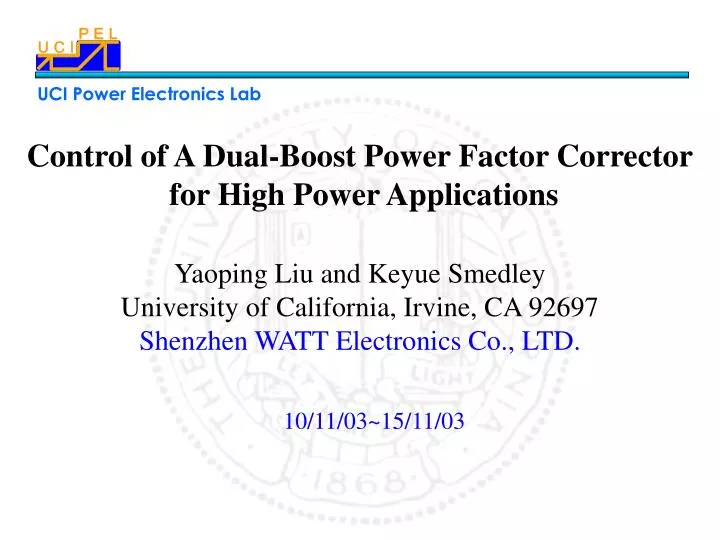
Control of A Dual-Boost Power Factor Corrector for High Power Applications. Yaoping Liu and Keyue Smedley University of California, Irvine, CA 92697 Shenzhen WATT Electronics Co., LTD. 10/11/03~15/11/03. Dual boost converter for high power PFC application PFC control method review

E N D
Control of A Dual-Boost Power Factor Corrector for High Power Applications Yaoping Liu and Keyue SmedleyUniversity of California, Irvine, CA 92697 Shenzhen WATT Electronics Co., LTD. 10/11/03~15/11/03
Dual boost converter for high power PFC application PFC control method review Proposed PFC control method for the converter (One cycle control method for PFC application) Stability analysis for the control method Experimental results Conclusions outlines
Popular configuration for practical power supply productions insulated uninsulated DC/DC VRM LOAD Vac PFC DC/DC SIP • Advantages: • Simpler circuit configuration; • adaptability to wide range input voltage; • higher efficiency; • relatively lower component stress. • But for higher power level application, the boost converter has some limitations PFC is necessary and very important for most of ac/dc power supply, and boost converter is used for single phase PFC:
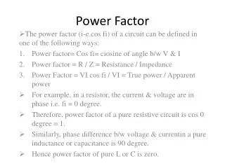
Dual boost converter for high level power PFC application When the converter operates under CCM, the conversion ratio is: • Traditional control method: • voltage follower approach; • large current stress, • significant residual current harmonics • Multiplier approach • circuit complex; • additional current distortion due to the nonlinearity of the multiplier • high cost • inconvenience of sensing the input voltage and the input current
The approach of PFC using PWM modulator Control goal: Vg = Re • ig Where Re is equivalent input resistor of DC/DC converter
occ core • CONSTRACTION: • A constant frequency • clock generator • A flip flop • An integrator with • reset switch • A comparator • The time coefficient of the integrator is selected to equal the switching period Ts; • V2 can be considered as constant during one cycle period; • For time t from the beginning of a cycle to the moment when v+ = v1, the duty ratio of Q is d. When d represents duty ratio for high and take as driver signal then:
The approach of PFC for the dual boost converter using OCC core V1= V2d Vm – Rs * ig = Vm* d Vm = RsVo/Re So control goal Vg = Re * ig is realized So control goal Vg = Re * ig is realized V1 = V2 (1 – d) Rs* ig = Vm (1 – d)
The stability analysis for the control method 1. The Stability Of The Trailing Edge Modulation. i.e. Define: if The duty ratio converges, so the stability condition is: Then, 2. The stability condition for leading edge modulation
A single-phase dual boost PFC rectifier using general constant frequency PWM control method is presented, And the converter can handle high power with a simple configuration; The multiplier and the sensor for input voltage are not needed; The control method is very simple and reliable which achieves low total harmonic distortion and high a power factor at low cost; Analyses for the topology and control method are provided, and experiment verification is provided. Conclusion