Download
1 / 22
220 likes | 422 Views
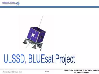
BLUEsat Telemetry and DTMF subsystem By David Lee 2252986 Supervisor Dr. J. Katupitiya. Overview Background My goal Design constraints System architecture Telemetry DTMF What I will do next Future of BLUEsat’s development. Background

E N D
BLUEsat Telemetry and DTMF subsystem By David Lee 2252986 Supervisor Dr. J. Katupitiya
Overview • Background • My goal • Design constraints • System architecture • Telemetry • DTMF • What I will do next • Future of BLUEsat’s development
Background • At the beginning of 2002, we had the chassis, radios, modem, the separation mechanism and some solar cells. • BLUEsat outsourced the flight computer development to CSE however they withdrew. • Faulty system architecture. • Unclear mission objectives and system specifications. • Veterans graduated and left the project. • Sounds pretty bad, doesn’t it?
My goal • Build the satellite while making sure I can graduate from UNSW • Figure out what needs to be done. • Electrical subsystem design parameter. • System architecture. • Continuing Daniel Faber’s work on telemetry system. • Start building the DTMF subsystem.
Design constrain Example, Power budget
Basic Design Concept • Dimension • Radiation • Reliability • Redundancy • Time • RF tolerance • Signal loss
Overall specifications Payload mass <5kg. Volume 40 40 30 mm for imager. 80 50 30 mm for GPS. 40 40 5 mm for solar test module. Power description: color-imaging camera 1 Coated Lexan UV experiment module. PERL/Buried contact solar cells test modules. Dimension: 230 225 240 mm Deployed Width: N/A BOL Wet Mass: < 15kg Dry Mass: > 10 kg + 13.2kg (launching plate) Power subsystem: 24 solar cell modules, 192 solar cells Battery not specified yet. Attitude Determination & Control: Passive magnetic stabilisation. Solar vane Z axis rotation Guidance & Navigation: GPS for time and speed determination.
Overall specifications (cont.) Telemetry, Tracking & Command: Uplink at 145MHz Downlink at 435MHz 9600 baud data transfer rate. Command and data handling: Standard PACsat protocol Propulsion: None Structure Characteristics: Aluminum chassis. Shape memory alloy separation system. Thermal Management: Solar modules are backed by a sheet of fiberglass and Aluminum honeycomb.
Role of telemetry subsystem Determine Roll rate Temperature Power input and output Orbital environment Diagnostics Chassis evaluation
How does the telemetry system works In general 64 sensors Temperature Voltage, current Radiation IR / UV 8 nodes I2C (Inter-integrated circuit) 2 wired bidirectional bus, 1 Data, 1 Clock 8 bit resolution required
Sensors allocations Example, tray 1
Telemetry subsystem design spec. Periodic time stamp/reset from GPS 16 bit Default time stamp at the beginning of every sampling cycle. 3 orbits worth of data needed for averaging 0.33 Hz sampling rate (optimal) Memory needed for 1 orbit: 119kB 3 orbits: 357kB Sampling scheme control by flight OS Must conform to Testing and Evaluation Master Plan
Telemetry driver, hardware and flight OS co-ordination Software Driver developed in C on RT Linux PC Communicate through PC parallel port, bit banging Get 12bit signal from node, reduce to 8 bit for storage
Telemetry subsystem hardware Hardware (from the left) PC running RT Linux Printer port adaptor (for testing) MAX127 Data acquisition chip board Sensors board
Role of DTMF Secondary command and control In case of Flight OS failure Manual control
How the DTMF works • In general • Combine 2 tones to represent a number, 0-9 & *#, A to D, can be modulated for transmission. • Timing is important. • On BLUEsat • Transmit a password and then the command to control • ON/OFF state of subsystems • Voltage supply to transmitter (Remove the excess power) • ROM banks selection of flight computer
What will I do next? Complete and test both subsystems!! Upgrade the existing nodes with I2C expander Debug the I2C driver! (haven’t fixed it, but I know I can and hence will fix it)
The future of BLUEsat development Recompile the driver for the future flight computer/s Lay the circuits down on PCB Integration with flight computer
Final Words Thanks for Everyone in BLUEsat Dr. Kat listen to my BS every week Have a nice day!
Q&A Dave Lee is too much bxxx sxxx……