Download
1 / 31
310 likes | 407 Views
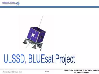
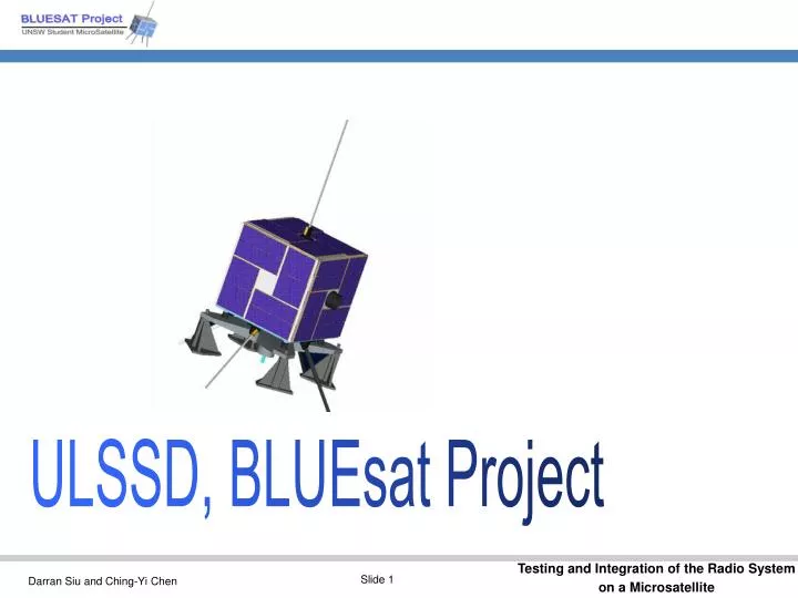
ULSSD, BLUEsat Project. Testing and integration of Radio Systems on a Microsatellite. Presented by: Darran Siu (2250276) Ching-Yi Chen (2272048) Supervisor: Dr. Keith Wiley Assessor: Dr. Jinhong Yuan. Introduction to the BLUEsat Project

E N D
Testing and integration of Radio Systems on a Microsatellite Presented by: Darran Siu (2250276) Ching-Yi Chen (2272048) Supervisor: Dr. Keith Wiley Assessor: Dr. Jinhong Yuan
Introduction to the BLUEsat Project What are the objectives of this thesis project Overview of testing and integration of the Radio Systems on this Microsatellite Scope and Progress Report to date Followed by questions from the audience… Overview of this presentation
BLUEsat Project • Basic Low Earth Orbit UNSW Experimental Satellite • Based on the AMSAT-NA microsatellite design • Mass: Less than 15 Kg • Size: 240 x 240 x 240mm (min)
BLUEsat Structure • Body mounted solar panels • Modular stack tray design • Spring loaded deployment mechanism • Passive magnetic stabilization
BLUEsat Subsystems Imaging system Flight Computer Communications Systems Power Management GPS Lexan Experiment
The reason for the chosen radio frequency range Amateur Radio Satellite Frequencies J mode — 145MHz uplink and 435MHz downlink Why? To avoid the pager interference that operates on 145MHz To avoid Asian Pirates (eg Taxi Companies) The Radio System
FM Transmitter & FM Receiver • Receiver • Model: Hamtronics R100 • Frequency: Receives at 145MHz • Data rate: 9.6Kbps • Main function— • Amplification • Selection and filtering • Frequency Demodulation • Frequency conversion • Transmitter • Model: Hamtronics TA451 • Frequency: Transmits at 435MHz • Data rate: 9.6Kbps • Main function— • Frequency Modulation • Frequency conversion • Amplification
Volunteer based Organisation Limited Resources Lack of Experience Lack of interfacing between sub-projects They have influence over our Thesis Project Problems with Student Engineering Projects
Validate/Establish of Requirements and Specifications of the Radio System To test the functionality of the radio system and its components. To integrate the system onto the microsatellite. Ensure the Radio System will survive launch and space environments To gain deeper knowledge of the satellite development and operation in space. Thesis Objectives
BLUEsat Power System BLUEsat Flight Computer System BLUEsat Interfaces Variable Controllable Voltage 13.6V – 9.1V Unregulated battery voltage 13.6V -> flat battery ~ 10V Serial Comm Link Audio In 2V P-P Modem/ TNC Audio Out 2V P-P RX 145 MHz TX 435 MHz THESIS SCOPE (Optional) Antenna System Antenna System RF 145 MHz In RF 435 MHz Out FM 145MHz any polarisation FM 435 MHz RHCP polarization Antenna System Antenna System Earth Equipment (the ground station) and Testing units TX 145 MHz RX 435 MHz
Particular Engineering Challenges with BLUEsat • Complex Space Systems Engineering • Lack of Knowledge • Expensive operation • Limited Resources • Lack of Experience
Requirements • Communicate to Groundstations • Transmit and Receive at 9600 bits per second • Allow Amateur Radio Operation • Transmit and Receive on Amateur Radio Bands • Comply with ITU and ACA Regulations • Fully operate under space conditions
Specification • Receiver receives at the frequency of 145MHz • Transmitter transmits at the frequency of 435MHz • The input DC voltage is between 9.1 to 13.6 volts. • The impedance of the antenna is 50 ohms.
Testing Plan • Functionality • Basic On/Off Test • Boundary Conditions • Physical limit of each component • Environmental • Temperature • EMI • Radiation
Functionality • Testing basic operation of each component. • Testing the basic functionality to see if it meets the spec values • Pass or Fail criteria • Static Free environment
Power DC input power Heat Generated RF performance Frequency Frequency drift effected by the temperature Doppler shift Boundary conditions • The maximum physical limits (and the range) of each component/system that it can be exposed to before breaking down
Environmental tests • Temperature Drifts • Vacuum • Electromagnetic Interference (eg Space Radar) • Cosmic Radiation • Heat Generated/Absorbed
Building the interfaces between The Power system Antennas The receiver and the transmitter Flight Computer/TNC Integrate the radio system onto the satellite Co-operate with other sub systems on the satellite Do the qualification and acceptance tests Integration
Use of Lab View software – Data Logger Test the radio system with the whole satellite Test the radio system against the boundary conditions Qualification Test Acceptance Test • Pre-Launch functionality test • Carry over the modifications
Considerable amount of heat generated Size restrictions Power Restrictions Bandwidth Restrictions Current problems encountered
Change the satellite Modify the components Downgrade our functionality Strengthen Components Use Space Grade Componentry Ensure ESD Free Environment Meticulous documentation and testing results Possible solutions
Progress report & work plan Phase 1:Defining the thesis scope Previous work from BLUEsat Phase 2: Literature review Interfaces from BLUEsat Sub-systems Phase 3: Validating & Establishing requirements Space Environment and knowledge Phase 4: Boundary Conditions Analysis Phase 5: Developing & Designing Test Plans
Progress report & work plan Phase 7: Space Environment Modification/ Hardening Fail Phase 6: Preliminary Component Testing Pass/Fail Pass Phase 8: Integration & Qualification Testing Fail Pass/Fail Pass Phase 9: Acceptance Testing Fail Pass/Fail Pass
We would like to thank all our generous sponsors and supporters for helping make this possible.
? Questions ? ?