Download
1 / 19
190 likes | 275 Views
Interference of waves. Coherent waves must have a constant phase difference. This means they must have the same frequency. Often the phase difference is zero but it doesn't have to be.

E N D
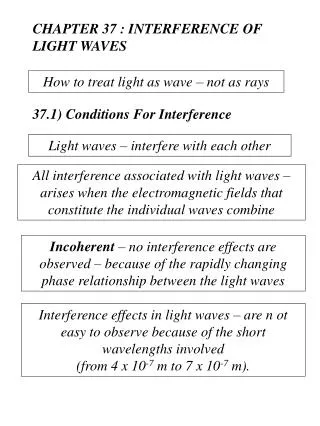
Interference of waves Coherent waves must have a constant phase difference. This means they must have the same frequency. Often the phase difference is zero but it doesn't have to be. Light is emitted by electron transitions within individual atoms. Thus waves from the same source will have the same frequency but will not be coherent as the phase difference will vary. (Except for laser light) For coherence the wave must come from the same position on the light source – division of wavefront. Or from the same wave which is split in two by reflection – division of amplitude
water Optical path length is the distance for the same number of wavelengths in a vacuum For interference in air (vacuum) Constructive path difference = n n = 0,1,2… Destructive path difference = ( n + ½) m m (m For interference in another medium we have to use the optical path difference.
A B The two rays have different geometrical path lengths but have the same optical path length. Ie they contain the same number of wavelengths. This means a lens does not affect the phase difference between rays
Refractive index n = vacuum material So vacuum = nmaterial Optical path length = n x geometrical path length Phase difference = 2 x optical path difference vacuum For interference in any material Constructive optical path difference = m m = 0,1,2… Destructive optical path difference = (m + ½)
Phase Change on Reflection glass air air glass Optically less dense ie. at a lower refractive index 0 radians phase change Optically more dense ie. at a higher refractive index radians phase change
1 2 air n=1 oil d n=1.45 water n=1.33 Examples of interference by division of amplitude 1. Parallel sided thin film At each boundary some light is reflected and some refracted. Someone looking at rays 1 and 2 would see an interference pattern. This is caused by path difference between the rays.
1 2 air n=1 oil d n=1.45 water n=1.33 If we assume the angle of incidence to be near 0 degrees, then the extra distance travelled by ray 2 will be 2d. This means that the optical path difference will be equal to 2nd However, there will be a phase change of λ/2at the first boundary (ray 1), since the ray is being reflected by a layer of greater refractive index The total optical path difference will be equal to? = 2nd + λ/2 For constructive interference the path difference must be equal to a whole number multiple of wavelengths 2nd +λ/2 = mλ 2nd = mλ – λ/2 = (m + ½) λ
For destructive interference the path difference must be equal to an odd number of half wavelengths. 2nd + λ/2 = (m + ½ ) λ 2nd = mλ + λ/2 – λ/2 For destructive interference, m=1 for minimum thickness.
Example Calculate the minimum thickness of oil which will produce destructive interference in green light of wavelength 525nm.
Blooming – non-reflective coatings If no light is reflected it will all be transmitted. For glass with a refractive index of 1.5 you would need a film of refractive index 1.22. Also this film must be durable. air coating glass As the refractive index of a material varies with frequency, the coating will only be non–reflective to one frequency. The non-reflective frequency is usually the middle of the visible spectrum so bloomed surfaces look purplish as some blue and red light will be reflected.
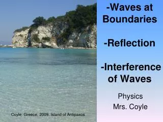
D Eye or travelling microscope Monochromatic light source A B t C x 2. Thin air wedge – used to measure small thicknesses Angle for the wedge is very small. The path difference between the two rays ABD and ACD is 2t.
3 Newton’s Rings Extended source Glass plate at 45o t A B B x Glass block – optically flat Fringes are concentric circles. Reflection at A zero phase change. Reflection at B p radians phase change Destructive interference 2t = ml m = 0,1,2… Constructive interference 2t = (m + 1/2)l Fringe at centre is dark.
Narrow slit gives circular waves Diffraction grating where coherent waves hit Monochromatic Source eg sodium lamp Division by wavefront dsin = m from Higher
Young's Slits Experiment The diagram below shows light from a single source of monochromatic light incident on a double slit. The light diffracts at each slit and the overlapping diffraction patterns produce interference.
The first bright fringe is observed at P. Angle PMO is θ N is a point on BP such that NP = AP Since P is the first bright fringe BN = λ For small values of θ, AN cuts MP at almost 900 giving angle MAQ = θ and hence angle ΒΑΝ = θ Again providing θ is very small, sin θ = tan θ = θ in radians
From triangle BAN: θ = λ / d and from triangle PMO: θ = Δx / D So λ / d = Δx / D Therefore
Two points to note: • This formula only applies if x<<D, which gives θ small. This is likely to be true for light waves but not for microwaves. • 2. The position of the fringes is dependent on the wavelength. If white light is used we can expect overlapping colours either side of a central white maximum. The red, with the longer wavelength, will be the furthest from this white maximum • (Δxred > Δxviolet since λred > λviolet).
Example A laser beam is incident on two narrow slits of separation (0.250 ± 0.002)mm. An interference pattern is produced on a screen (2.455 ± 0.005)m from the slits. The spacing across ten fringes is measured as (62.0 ± 0.5)mm. (a) Calculate the wavelength of the light. (b) State the uncertainty in the wavelength and express the wavelength as (value ± absolute uncertainty). Δx = 62.0x10⁻³/10 Δx= λD/d 62.0x10⁻³/10 = λx2.455/0.250x10-3 λ=631nm Using % uncertainties: Uncertainty in d =(0.002/0.250)x100=0.8% Uncertainty in D=(0.005/ 2.455)x100=0.2% Uncertainty in Δx=(0.5/62.0)x100=0.8%
The uncertainty in D can be ignored since it is less then one third of the others. Total % uncertainty is = √( 0.82 + 0.82) = 1.1% 1.1% of 631nm = 7nm so wavelength = (631 ± 7)nm (d) State, with a reason, if the fringe spacing increases, decreases or remains the same if red laser light is replaced by a Helium-Cadmium laser with a wavelength of 422nm. (e) State one way in which you might be able to improve the accuracy of the experiment, give a reason. Since the wavelength has decreased the fringe spacing decreases, since Δx λ Measure across more fringes, for example twenty fringes. This would reduce the percentage uncertainty in Δx.