Download
1 / 23
230 likes | 237 Views
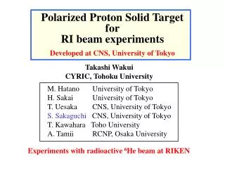
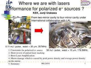
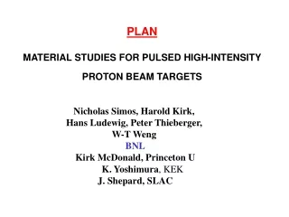
Parameters of the NF Target Proton Beam pulsed 10-50 Hz pulse length 1-2 ms energy 2-30 GeV average power ~4 MW Target (not a stopping target) mean power dissipation 1 MW energy dissipated/pulse 20 kJ (50 Hz) energy density 0.3 kJ/cm 3 (50 Hz). beam. 2 cm.

E N D
Parameters of the NF Target Proton Beam pulsed 10-50 Hz pulse length 1-2 ms energy 2-30 GeV average power ~4 MW Target (not a stopping target) mean power dissipation 1 MW energy dissipated/pulse 20 kJ (50 Hz) energy density 0.3 kJ/cm3 (50 Hz) beam 2 cm 20 cm
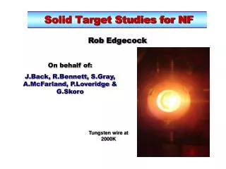
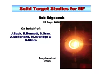
Schematic diagram of the RALradiation cooled rotating toroidal tantalum target rotating toroid toroid magnetically levitated and driven by linear motors solenoid magnet toroid at 2300 K radiates heat to water-cooled surroundings proton beam
The New Programme • Since NuFact04 the R&D programme has altered significantly: • Simulate shock by passing a pulsed current through a wire. • Measure the radial motion of the wire to evaluate the constitutive equations (with 3.). • Use a commercial package, LS-DYNA to model the behaviour. • Life time/fatigue test. 50 Hz for 12 months. • Investigate the possibility of widely spaced micro- bunches of proton beam to reduce the shock impact.
Proposed R&D (2004) • Calculate the energy deposition, radio-activity for the target, solenoid magnet and beam dump. • Calculate the pion production (using results from HARP experiment) and calculate trajectories through the solenoid magnet. • 2. Model the shock • a) Measure properties of tantalum at 2300 K. • b) Model using hydrocodes developed for explosive applications at LANL, LLNL, AWE, etc. • c) Model using dynamic codes developed by ANSYS. • 3. Radiation cooled rotating toroid • a) Calculate levitation drive and stabilisation system. • b) Build a model of the levitation system. • 4. Individual bars • a) Calculate mechanics of the system. • b) Model system. • 5. Continue electron beam tests on thin foils, improving the vacuum. • 6. In-beam test at ISOLDE - 105 pulses. • 7. In-beam tests at ISIS – 107 pulses. • 8. Design target station.
Shock, Pulse Length and Target Size When a solid experiences a temperature rise the material expands. Because of mass inertia there will always be a slight lag in the expansion. This causes pressure waves to ripple through the material. When the temperature rise is relatively large and fast, the material can become so highly stressed that there is permanent distortion or failure - shock. Short high intensity beam pulses will give rise to shock in a target. The shock wave travels through matter at the speed of sound, where E is Young's modulus of elasticity and ρ is the density.
The time taken for the wave to travel from the outer surface to the centre is given by If the beam pulse (τp) is long compared to the characteristic time τs, then little energy goes into the target in this time and the shock wave in the target is reduced. If the target is small compared to the beam pulse length the shock is reduced. If No problem! Must have sufficient pulsed energy input!
The Proton Pulse micro-pulse macro-pulse • Proton beam “macro-pulses” and “micro-pulses”. • Traditionally we have considered the micro-pulses as ~1 ns wide and the macro-pulses as ~1 s wide. The temperature rise per macro-pulse is ΔT~ 100 K. • For the tantalum bar target, radius 1 cm and length 20 cm, then: • The time for the shock wave to travel a radius is 3 ms • The time for the shock wave to travel a half the length is 30 ms • However, in the RAL proton driver scheme with ~10 micro-pulses, it is likely thatthey could be spaced apart by ~40 s, thus reducing the effective thermal shock to only ΔT ~ 10 K.
NF Target: 1 cm radius 20 cm long t = 3 s Total temperature rise: DT = 100 K Effect of 10 micro-pulses in 1 and 5 ms long macro-pulses. Goran Skoro, Sheffield University
Pulse Heating Pulsed ohmic-heating of wires can replicate pulsed proton beam induced shock. current pulse tantalum wire Energy density in the wire needs to be ε0 = 300 J cm-3 to correspond to 1 MW dissipated in a target of 1 cm radius and 20 cm in length at 50 Hz.
Transient Conditions • Assume an electric field E is instantaneously applied across a conducting wire. • Apply Maxwell’s equations. • This produces a diffusion equation: • In cylindrical coordinates, where j is the current density. • The solution is: = 1/0
The Velocity of the Shock Wave • Shock travels at the Speed of Sound. • Can only use small diameter wires of up to ~0.4 mm to get current penetration into the wire. • “Choose a better material”
Characteristic Times for the shock to travel across the radius and for the current to penetrate the wire (square pulse). 10000 τs τI ns 1000 100 10 0.1 a, mm 1
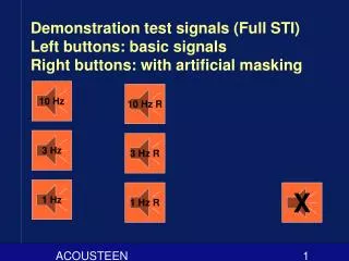
Doing the Test The ISIS Extraction Kicker Pulsed Power Supply Exponential with 20 ns rise time fitted to the waveform Voltage waveform Time, 100 ns intervals Rise time: ~100 ns Voltage peak: ~40 kV Repetition rate up to 50 Hz. Flat Top: ~300 ns Current Peak: ~8 kA There is a spare available for use.
1000 ns 100 ns j/j0 30 ns 10 ns 1 ns r/a Current density versus radius at different times. Wire radius, a = 0.3 mm.
j/j0 0.1 mm 0.2 mm 0.3 mm 0.4 mm 0.6 mm , s Current density at r = 0 versus time (t, s), for different wire radii (a, mm).
The average current density over the wire cross section versus time (t, s), for various wire radii, (a, mm). 0.4 0.5 0.3 1 mm 0.2 0.1
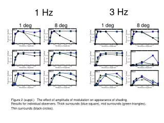
Effect of different pulse lengths (shown by arrows), for exponential current rise of 30 ns. Goran Skoro, Sheffield University.
Effect of different pulse lengths (shown by arrows), for exponential current rise of 30 ns. Goran Skoro, Sheffield University.
Radius Characteristic time Energy density mm τs, ns MJ m -3 0.1 30 323 0.2 60 69 0.3 90 21 0.4 120 8 0.5 150 3.4 0.6 180 1.6 0.7 210 0.8 0.8 240 0.4 0.9 270 0.2 1.0 300 0.1 The energy density dissipated at the centre of the wire, within a time τ for s different wire radii, with I = 10000 A. 0 Energy Density in the Wire
Radius Characteristic time Current mm τs, ns I0, kA 0.1 30 10 0.2 60 21 0.3 90 37 0.4 120 61 0.5 150 94 0.6 180 138 0.7 210 197 0.8 240 273 0.9 270 373 1.0 300 499 Pulse Current Requirements The current, I0, required to dissipate 300 MJ m-3 at the centre of the wire within a time τs, for different wire radii.
heater insulators to pulsed power supply to pulsed power supply test wire water cooled vacuum chamber to vacuum pump or helium gas cooling Schematic diagram of the test chamber and heater oven.