Download

1 / 41
410 likes | 591 Views
Chapter 10 Heat Exchangers 换热器热. 10 -1 Introduction. Three modes of heat transfer conduction convection radiation We study separately Integrated application Technical analysis Economic gain Sustainable development. 10-2 The overall heat transfer coefficient.

E N D
10-1 Introduction • Three modes of heat transfer • conduction • convection • radiation • We study separately • Integrated application • Technical analysis • Economic gain • Sustainable development
10-2 The overall heat transfer coefficient • definition of the overall heat transfer coefficient • a plane wall
h1 and h2are calculated with the method in previous sections • Combined Heat Transfer (Radiation heat transfer) 1). Calculation of heat transferred by radiation qr 2). Defining 3). then 4). Total heat flow rate
tubes The overall heat transfer coefficient based on inside area of the tube The overall heat transfer coefficient based on outside area of the tube
open wall • fin-wall combinations
10-3 Fouling factors Fouling (污垢)---The coating of various deposit on heat transfer surfaces Fouling provides an additional thermal resistance which is called fouling thermal resistance or Fouling Factor. An alternative definition Plane wall Outside surface of a tube
linear 渐进污垢热阻 asymptotic fouling resistance falling 渐进 induction period(诱导期) • Example:Water side of a condenser Rf=0.00035m2K/W • convection resistance • outside of tube 28.3% • wall resistance 3.3% • fouling resistance 34.2% • convection resistance • inside of tube 34 .2%。 The extra area may be 100% Recommended values of the fouling factors are given by the TEMA (Tubular Exchanger Manufactures Association) standard
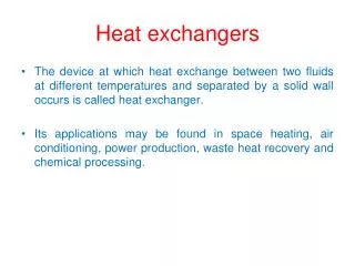
10-4 types of heat exchangers • Definition • A heat exchanger is a device, such as an automobile radiator, used to transfer heat from a hot fluid to a cold fluid. 2. Types • Direct-contact Heat Exchanger (混合式): heat transferred by the mixing of hot and cold fluids. Deaerator (除氧器), spray type desuperheater (喷水减温器) • Direct-transfer-type Heat Exchanger (间壁式):A heat exchanger transfers heat from a fluid on one side of a barrier to a fluid on the other side without bringing the fluids into direct contact. Widely used,economizer, superheater, reheater etc. • regenerative heat exchanger (蓄热式or回热式): air preheater (空气预热器)
3. Types of Direct-transfer-type Heat Exchanger (1). Double Tube Heat Exchanger (套管式) (2). Shell and Tube Heat Exchanger (壳管式)。
Tube Pass (管程) • Shell Pass (壳程) • Number of tube pass 管程数 • Number of tube pass 壳程数 • Naming 壳程数-管程数 • 1-2型:壳程为1,管称为2;2-4型:壳程为2,管称为4。 • Parallel Flow (顺流) • Counter Flow (逆流) • Cross Flow (交叉流) • If the two fluids cross each other more than four times, the heat exchangers could be taken as parallel of counter flow.
10-5 The Logarithm Mean Temperature Difference (对数平均温差 ) LMTD The heat transferred We used arithmetic mean temperature difference. Is it right?
Subscript h---hot fluid c---cold fluid 1---inlet 2---outlet 1. Assumptions: • the heat capacities of hot and cold fluids are constant • U=constant; • the heat exchanger is insulated (no heat loss to surroundings) • negligible heat conduction in the direction of flow • the changes of kinetic energy are negligible • if either fluid undergoes a change of phase, then this phase change occurs throughout the heat exchanger—not in just a portion of the heat exchanger • at any cross section in the heat exchanger, each of the fluids nay be characterized by a single temperature
2. LMTD of a parallel flow heat exchangers The heat transfer through an element of area Heat balance Combining
Separating variables integrating or When Ax=A, tx= t2, Substituting into eq
3. LMTD of counter flow heat exchangers For a counter heat exchanger show in fig. if is taken the following form One can obtain a similar eq. The temperature difference at one end of the heat exchanger less the temperature difference at the other end of the exchanger divided by the natural logarithm of the ratio of these two temperature differences.
Arithmetic mean temperature difference It is always greater than LMTD
arithmetic mean temperature difference is always greater than LMTD • when tmax/ tmin approaches to 1, the difference becomes small • when tmax/ tmin2,the difference is less than 4% • whentmax/ tmin 1.7,the difference is less than 2.3% • according to the standard of boiler,when tmax/ tmin 1.7, arithmetic mean temperature difference could be used instead of LMTD
4. LMTD of other type of heat exchangers If a heat exchanger other than parallel or counter flow type is used, the heat transfer is calculated by using a correction factor applied to the LMTD for a counter flow heat exchanger with the same hot and cold fluid temperatures. The correction factor is the function of P and R F=f (P,R) Which may be obtained according the figures 10-8 to 10-11. Notice the definition of Pand R.
counter flow parallel flow • for condensers and evaporators, parallel or counter flow are the same • generally the LMTDparallel flow< LMTDother < LMTD counter flow • F<1, F ,A ,usually F>0.8
5. The temperature profiles • Why the hot temperature profile of a parallel flow heat exchanger is concave? Could it be convex? • Parallel flow A↑ ↓ ↓ So are constant, then dq↓ dth、dtc↓ That is to say as the increase of the area A,the changes of temperatures decrease.
dA • counter flow • when qmhch >qmccc, th < tc A↑ tx ↑ d Φ =ktxdA↑ ↑ ↑ • the profile is convex • When qmhch <qmccc , Th> Tc • A↑ tx↓ d Φ↓ d th d tc↓ • the profile is concave
When th= tc two parallel lines
6. Calculation of the performance of a heat exchanger • Basic equations The heat transferred may be expressed in three ways • The overall heat transfer coefficient (previous sections)
Types of the performance calculation 1). According to the calculation purpose (1). Design Calculation (设计计算) determining the heat transfer area Three ofth1, th2, tc1, tc2, qmhch ,qmccc are specified, what is the F? (2). Checking Calculation (校核计算), checking whether a given heat exchanger could work under certain condition. are specified What are the values of the outlet fluid temperatures thoor tco and what is the total amount of heat transferred
2). According the calculation method (1). LMTD approach (平均温差法) (2). -NTU(效能-传热单元数法) • LMTD approach The calculation is based on the basic equations 1). The procedure of design calculation (1). Arrange the configuration, calculate the corresponding k (2). Solve for unknown temperature from heat balance (3). Calculate LMTD,notice the correction factor F (>0.8) (4). Calculate the heat transfer area A,check the pressure drop (5). If the pressure drop is too large, rearrange the configuration and repeat the process
2). The procedure of checking calculation (1). Assume eithertho andtcoand compute the other from heat balance; (2). Calculate LMTD; (3). Calculate the overall heat transfer coefficientkfrom the configuration; (4). Find Φbased on k, A and tm; (5). FindΦfrom either energy change of hot fluid and cold fluid; (6). Compare these twoΦ’s obtained from step (4) and (5). If the difference is greater than 2-5%, repeat the computations, starting with step (1), until the difference is less than 2%5%.
10-6 Effectiveness-NTU method • The disadvantages of the LMTD approach • F=(P,R), sometimes dF/dP , F is difficult to be determined • The assumed outlet temperature has large influence on heat balance. • An iteration is needed
Definitions • (1). Heat Exchange Effectiveness (换热器的效能) (2). Number of Transfer Units (传热单元数) (3). Capacity Rate (热容量)
Effectiveness 1) For parallel heat exchanger, if the cold fluid is the minimum from the definition of Heat balance then eq. (a) + (b)
from eq.(10-10) where Substituting into eq. (c) When hot fluid is the minimum, one can gain in a similar way General expression
A similar analysis may be applied to the counter flow case. NTU is a dimensionless group indicating the size of the heat exchanger When one of the fluid undergoes phase change (boiler & condenser),that is Cmax,or Cmin/ Cmax0, all the heat exchanger effectiveness relations approach a single simple equation If Cmin/ Cmax=1 Parallel flow Counter flow
The effectiveness for various heat exchanger arrangements is given in Figures 10-12 to 10-17, Table 10-3 and 10-4 • The heat transferred
Example: A counter flow double pipe heat exchanger is well insulated. The outside diameter of inner tube is do=25mm, the thickness =1.5mm,the thermal conductivity k =109W/(m·K). Oil flows through the inner tube with th1=70C,Vh=55 l/min =0.917×10⁻³ m3/s,h =838kg/m3,ch=2.07kJ/(kg·K),convection heat transfer coefficient hi=420W/(m2 ·K). Water flows through the annular space with Tc1=15 C,Vc=116l/min=1.93 ×10-3 m3/s,ho=5859W/(m2 ·K),cc=4.2kJ/(kg·K); c=1000kg/m3. Calculate the outlet oil temperature th2。 Solution 1-NTU method
Solution 2:LMTD method Assume Heat balance Solve for and Reassume Repeat the above steps, one has