Download
1 / 38
2.46k likes | 6.93k Views
HYDRO ELECTRIC POWER PLANT. AGUS HARYANTO. WHAT IS HYDRO POWER?.

E N D
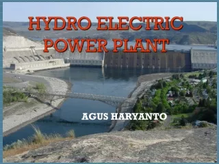
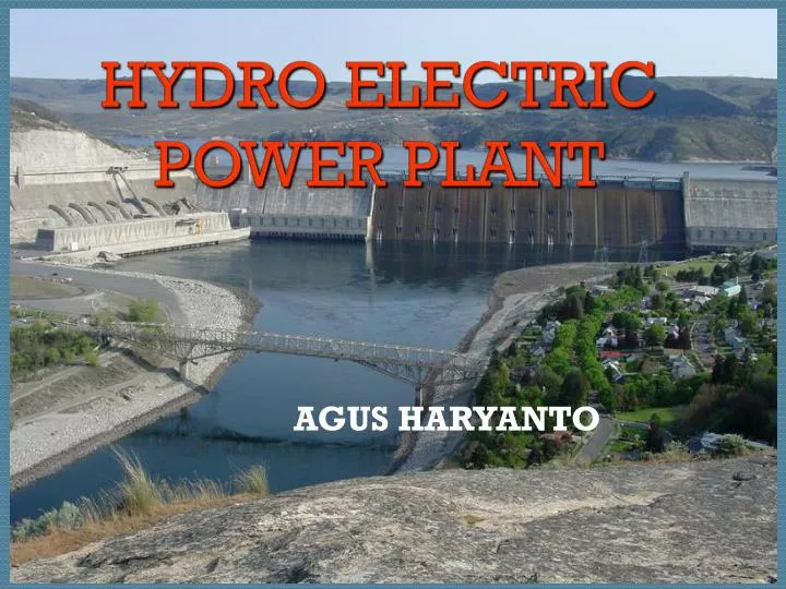
HYDRO ELECTRIC POWER PLANT AGUS HARYANTO
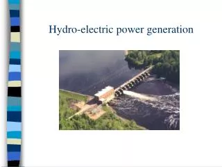
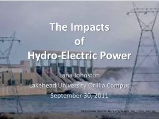
WHAT IS HYDRO POWER? The objective of a hydropower scheme is to convert the potential energy of a mass of water, flowing in a stream with a certain fall to the turbine (termed the "head"), into electric energy at the lower end of the scheme, where the powerhouse is located. The power output from the scheme is proportional to the flow and to the head.
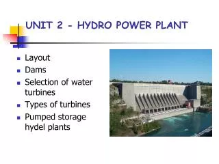
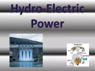
ELEMENTS OF HYDRO POWER POWER HOUSE PENSTOCK DAM TURBINE GENERATOR RESEVOIR INTAKE POWER LINE TRANSFORMER
DAM:- • The movement of water can be used to make electricity. Energy from water is created by the force of water moving from a higher elevation to a lower elevation through a large pipe penstock). When the water reaches the end of the pipe, it hits and spins a water wheel or turbine. The turbine rotates the connected shaft, which then turns the generator, producing electricity.
INTAKE:- A water intake must be able to divert the required amount of water into a power canal or into a penstock without producing a negative impact on the local environment.
INTAKE:- “Conveying water from the intake to the power house”.The water in the reservoir is considered stored energy (potential energy). When the gate opens the water flowing through the penstock becomes kinetic energy because it is in motion.
Turbine • The water strikes and turns the large blades of a turbine, which is attached to a generator above it by way of a shaft. The most common type of turbine for hydropower plants is the Kaplan Turbine, Francis Turbine, and Pelton Turbine.
Kaplan turbines • Low head (from 70 meter and down to 5 meter) • Large flow rates • The runner vanes can be governed • Good efficiency over a vide range
Francis turbines Heads between 15 and 700 m. Medium Flow Rates Good efficiency = 0.96 for modern machines
Pelton turbines • Large heads (from 100 meter to 1800 meter) • Relatively small flow rate • Maximum of 6 nozzles • Good efficiency over a vide range
Jostedal, Norway *Q = 28,5 m3/s *H = 1130 m *P = 288 MW
Tailraces:- After passing through the turbine the water returns to the river trough a short canal called a tailrace.
Generator As the turbine blades turn, so do a series of magnets inside the generator. Giant magnets rotate past copper coils, producing alternating current (AC) by moving electrons. Basic parts of generator : 1. Shaft 2. Excitor 3. Rotor 4. Stator
Inside the Generator:- The heart of the hydroelectric power plant is the generator. The basic process of generating electricity in this manner is to rotate a series of magnets inside coils of wire. This process moves electrons, which produces electrical current.
Excitor As the turbine turns, the excitor sends an electrical current to the rotor. The rotor is a series of large electromagnets that spins inside a tightly-wound coil of copper wire, called the stator. The magnetic field between the coil and themagnets creates an electric current.
Transformer is a device that transfers electrical energy from one circuit to another through a shared magnetic field. A changing current IP in the first circuit (the primary) creates a changing magnetic field; in turn, this magnetic field induces a voltage VS in the second circuit (the secondary). The secondary circuit mimics the primary circuit, but it need not carry the same current and voltage as the primary circuit. Instead, an ideal transformer keeps the product of the current and the voltage the same in the primary and secondary circuits.
7TH ELEMENT OUTFLOW:- Used water is carried through pipelines, called tailraces, and re-enters the river downstream.
POWER HOUSE & EQUIPMENTS:- In the scheme of hydropower the role of power house is to protect the electromechanical equipment that convert the potential energy of water into electricity. Following are the equipments of power plant:1.Valve 5.Condensor 2.Turbine 6.Protection System3.Generator 7.DC emergency Supply4.Control System 8.Power and current transformer
Closing Remark Flowing water creates energy that can be captured and turned into electricity. This is called hydropower. Hydropower is currently the largest source of renewable power, generating nearly 10% of the electricity used in the United States. The most common type of hydropower plant uses a dam on a river to store water in a reservoir. Water released from the reservoir flows through a turbine, spinning it, which, in turn, activates a generator to produce electricity. But hydropower doesn't necessarily require a large dam. Some hydropower plants just use a small canal to channel the river water through a turbine.
CONTOH SOAL Sumber air padaketinggian h = 14 ft memberikan debit Q = 9 ft3/dtuntukmenggerakkankincir air berdiameter D = 12 ft. Kincir air berputarpadakecepatan N = 5 RPM danmemiliki 36 buahmangkuk yang terisi air tidaklebihdariseparohnya. • Berapakah volume tiapmangkuk? • Bilaluaspenampangmangkuk 1.2 ft2, berapalebarkincir? • Berapakecepatanspesifik? (Asumsi = 60%)
SOLUSI • Volume mangkuk: N = 5 RPM Tiap putaran = 12 dt Q = 9 ft3/dt Vol air jatuh tiap putaran = (9 ft3/dt)*12 dt = 108 ft3 Vol tiap mangkuk = • Lebar kincir = 6 ft3/1.2 ft2 = 5 ft
SOLUSI (CONT) • Daya yang dihasilkan: P = Q g h = (60%)(9 ft3/dt)(62.4 lb/ft3)(14 ft) = 4717.4 ft.lb/dt = 8.58 Hp • Kecepatan spesifik Ns = (5)(8.58)0.5(14)-1.25 = 0.54
TURBIN RODA PELTON • Kecepatan jet: C = koefisien transmisi • Kecepatan titik di luar roda Pelton U = a.V a = konstanta U = DN • Daya = Q g h
CONTOH SOAL SebuahrodaPeltondipakaiuntukmenghasilkandayadari air berketinggian h = 14 ft. Jika U = 0.45 V dengan V adalahkecepatan jet air padanozel. N = 300 RPM. Pertanyaan: • Berapa diameter rodaPelton? (Asumsi C = 0.95) • Bila diameter nozel 2 in, berapa debit air? • Berapadaya (HP) jikaefisiensi 88%? • BerapakecepatanspesifikrodaPelton?
SOLUSI • Diameter roda Pelton V = 0.95 = 66 ft/dt U = 0.45 V = 0.45(66) = 29.7 ft/dt D = U/N = 29.7/(0.88*300) = 1.89’ = 22.7”
SOLUTION (Cont) • Debit air Q = A.V Anozel = d2/4 = (2/12)2/4 = (/144) ft2 Q = A.V = (/144) ft2 (66 ft/dt) Q = 1.44 ft3/dt • P = Q g h = (0.88)(62.24)(1.44)(75)/550 P = 10.78 HP
SOLUTION (Cont) • Ns = N(Daya)0.5 (h)-1.25 Ns = 300(10.78)0.5 (75)-1.25 Ns = 4.46 Note: Ns optimum untuk turbin roda Pelton adalah 5