Download
1 / 26
260 likes | 273 Views
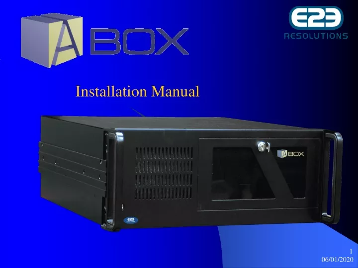
Installation Manual. Table of contents:. Basic Steps Procedure page 3 System Overview A-Box Components page 4 Typical A-Box setup Using High speed connection page 5 Using Dial up connection page 6 Set up communication network Connecting SURELINK modules page 7

E N D
Table of contents: Basic Steps Procedure page 3 System Overview A-BoxComponents page 4 Typical A-Box setup Using High speed connection page 5 Using Dial up connection page 6 Set up communication network Connecting SURELINK modules page 7 SURELINK PCB layout page 8 SURELINK setting EOL jumpers page 9 Building your A-Box and Controllers Network Building your network I page 10 Building your network II page 11 Building your network III page 12 Platform-IC (PIC) Platform -IC Installation procedure page 13 Platform -IC Installation procedure II page 14 Platform-IC installation procedure III page 15 Setting-up your communication network page 16 Enabler Cards Setting up ID numbers page 17 Dip Switch positions I page 18 Dip Switch positions II page 19 Dip switch positions III page 20 Enabler card installation page 21 Led` s status page 22 Accessing the A-Box Using a modem connection page 23 Using a High speed connection page 24 Battery backup Installation procedure page 25
Basic Steps Shipment verification Every A-box installation package should contain the following items in it: A-Box, Sure Link modules, Sure Link AC-transformers, Enabler cards, Platform-IC, Configuration Sticks, Battery backup unit, RS-485 Communication cable DB-25/2 X DB-9, RS-485 communication cable DB-9, Wireless Router Network layout (drawing) Specify # of barns, or houses, # of rooms ,# of floors and zones, # of controllers, locate a place to mount the SureLink modules , assign ID # and set-up EOL jumper on each Enabler card This procedure will help you to build up your network and eventually to complete the A-Box Commissioning process. Wiring check-up Verify the wiring, starting from the A-box all the way to the last controller on the network, make sure there is always continuity at each junction point. Note that the communication cable should have 3 conductors 2 for communication and a 3rd conductor could be the drain or shield . Enabler Card and Platform-IC installation Ones the network layout has been drawn and you hade checked the wiring then you can proceed with the Enabler card and Platform-IC installation, this procedure is detailed on this document please read carefully and if you have any question feel free and contact the E2E technical support department who will assist you thru this process at any time
System Overview A-BOX system components Router Enabler Card Platform-IC SureLink AC-Transformer Power Back-Up RS-485 Adaptor SureLink Fig A
Typical A-BOX SetupUsing High speed internet connection Fig B
Connecting SureLink Modules In Order to protect your controllers and A-BOX against lightning, you must install a SureLink module at the entrance and at the exit of each building. The first SureLink module: Must be connected close to the A-BOX as illustrated on fig D. Refer to the SureLink ‘s manual to get further information about SureLink modules. Connect the RS-485 connector (DB-25) to the RS-485 adaptor of the A-BOX. This cable has a RS-485 connector (DB-25) at one end and has two DB-9 connectors at the other end (connectors A&B). There is a RS485 cable with 3 conductors at one end and a DB-9 connector at the other, this cable is supply with the A-Box installation package. Connect the 3 conductors end at the Sure Link nearest to the A-Box and the DB-9 end to the DB-9 Connector (A) as seen on fig “D”. The DB-9 connector (B) is used for a 2nd network Ex . If you have a ventilation AND Feed-Link network Fig D
SURELINK PCB The picture below shows a SURELINK unit and its typical wiring Installation holes Under rubber caps Fig E
End Of Line JUMPERS EOL -(J1 & J2) SURE LINK EOL JUMERS: The SureLink’s EOL connector its mounted on the PCB itself see fig below J1 & J2 Each SureLink module deals with 2 separate networks: devices that are connected to terminals to the right side of the electronic board are on a different network than those connected to the left. Set EOL jumpers separately for each network of the SureLink. Exceptionally the EOL jumper must be set to “NO” on the A-Box network (J1 position 1-2) Setting End Of Line EOL jumpers EOL JUMPERS RED WIRE Black wire FIG F Shield
Building your Network SURELINK MODULE : One network on one barn Fig G NETWORK- A
Building your network II SURELINK MODULE: FOUR DIFFERENT NETWORKS A,B,C,D ON THREE DIFFERENT BARNS NETWORK-A Fig H
Platform-IC Installation procedure I This section will explain you how to replace the Platform-IC on every controller of your network. The location of the P-IC varies from one controller to the other in some controllers de P-IC is located behind the display control panel, Fig M and N some others have an easy access like fig O. Fig O Fig M Fig N
If your controller looks like the previous page Fig-M and N then the procedure to remove the Platform-IC is the following: Step-1 Disconnect the 34 pins flat ribbon cable fig -P that supply its voltage, to prevent any short circuit. STEP -2 Remove the screws that hold the main DISPLAY control panel, To remove the existing Platform-IC you will need a PLC extractor see fig -Q . And fig R. Step -3 Insert the new Platform-IC: make sure to insert the Platform-IC on the right position please see Fig-R1. It’s important to respect the Platform-IC polarity. Step -4 Put back the display control panel screw it down and plug back-in the 34 pins flat ribbon cable Platform-IC installation II Fig. P Fig. Q IC-socket polarity reference IC-Polarity reference Click on IC Fig R FIG-R1
Replacing the Platform-IC part II • If your controller looks like the one on Fig- S then follow this procedure to replace the Platform-IC: • Step -1 • Remove the 34 pin flat ribbon cable • Step-2 • Use the PLC extractor to remove the Platform-IC from its socket • Step -3 • -Insert the Platform-IC , be careful at the insertion to keep the right polarity. • Step -4 • -Reconnect the 34 pins flat ribbon cable Platform-IC Installation part III Fig S IC-socket reference point IC reference point Fig T Click on IC
Setting-up your communication network SETTING UP CONTROLLERS: In order to communicate with the A-BOX An “Enabler” communication card must be plugged in each controller. This section explains how to connect controllers on the communication line and how to set up their Enabler cards. CONNECTING THE CONTROLLERS: This procedure show how to connect various controllers to the communication line . The communication cable may be extended up to 6000 feet (1800 meters) if the wire diameter is at least of 22 AWG. The recommended wire for communication is 1 twisted pair shielded cable 18AWG. The first environment controller must be connected to the first SureLink module as illustrated on fig “J”. Only one controller can be connected to this module. Connect all following controllers in series to their PC1 & PC2 terminals. STAR CONNECTIONS ARE NOT ALLOWED FIG J
Setting up ID numbers The A-Box establishes communication with the controllers through their Enabler cards. In order to distinguish the controllers, the A-Box refers to the specific identification number assigned on DIP SWITCH S1 to each Enabler card For this reason, You must assigned a unique ID number to the Enabler card of each controller following numerical order. Start identifying the controllers with ID #2 and do not skip any number between two consecutive Enabler cards. Identification numbers range from ID #2 to 253. ID #1 it’s reserved to the A-Box. LED #2 LED #1 DIP SWITCH S1 LED #3 LED #4 Fig L
Enabler cards Installation SET-UP ENABLER END OF LINE (EOL) JUMPER (J3) . The EOL jumper its located on its “Enabler card”. You must specify the first and last device on the network by setting end of line jumpers Set to “YES” (positions 2-3 - see Fig-K) on the first and last Enabler card; set to “NO” position on the rest of the Enabler cards on a specific network . PROCEDURE : slide-in the Enabler card 20 pins female connector J2 into the controller’s 20 pins male connector. J3 J2 Fig K
The “Enabler” card has 4 LED’s on board , each one of them have different status: -- Enabler card’s software status -- Communication link between the A-Box and the controllers’ s status -- The data transfer status. Status LED’s are numbered from 4 to 1 see fig “L”, These LED’s are mostly used by the installer to troubleshoot the communication system The table below gives the detail of the flashing LED’s status LED’S STATUS
Accessing the A-Box using Modem connection Way #1 (Dial-up connecting A-Box thru internet Step-1 Connect the telephone line to the A-Box internal modem, bottom inlet. Step-2 Configuration -The internet configuration should be done thru the commissioning process. Please refer to the commissioning document by E2E Resolutions. Way#2 Dial-In Connection Step-1 connect the telephone line to the A-Box internal modem bottom inlet. Step-2 Configure your computer connection thru the Windows utility please refer to the commissioning document by E2E resolutions Telephoneline Fig U
Accessing the A-Box using High speed modem and a router Connect a standard Ethernet network cable to Ethernet port of the A-BOX. Then, connect the other end of the Ethernet cable to one of the numbered Ethernet ports on your Link-Sys router. Connect standard Ethernet network cable to the Router’s INTERNET PORT. Then, connect the other end of the cable to your high speed modem . The router supply with your installation package, allows the A-Box to operate on a separate network giving a complete access to Internet. At the same time will allow anyone near the ROUTER using wireless connection like portable computers have access to the A-Box and Internet. See fig V. ISP-IN Ethernet ports Ethernet Port Fig V
Back-UPS installation Before plugging the A-BOX to the UPS, be sure the UPS`s battery is properly connected. Refer to the UPS’s manual, section 1. -Plug the Back-UPS ES power cord directly into a wall outlet; not a surge protection or power strip -Connect the female end of the A-BOX power cord into the power outlet behind the A-BOX -plug the other end into a power outlet located on the BATERY BACKUP PLUS SURGE PROTECTION side of the UPS. -Plug the RJ45 jack of the USB cable, supplied with your UPS package into the Data Port of the UPS. -Plug the other end of the USB cable into any of the USB ports at the back of the A-BOX. Fig W