Download

1 / 6
60 likes | 207 Views
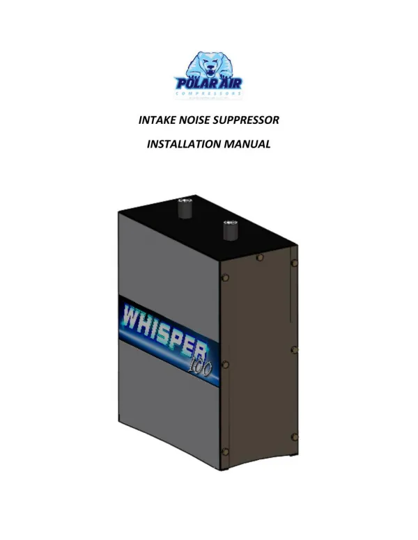
Here are the installation instructions for Intake Noise Suppressor in Whisper 100 compressors along with the parts list. You will start by removing existing filter assembly/assemblies from compressor pump. <br><br>For full procedure, refer: https://www.eatoncompressor.com/whisper-100<br>

E N D
INTAKE NOISE SUPPRESSOR INSTALLATION MANUAL
PARTS LIST PART NUMBER DESCRIPTION QUANTITY PICTURE 1” STREET L 2 FITTING029 FITTING034 1” NPT PLUG (OPTIONAL) 1 FITTING082 1” NPT MALE X 1” BARBED 4 FITTING024 ¾” NPT NIPPLE 1 1/8” LONG (OPTIONAL) 2 FITTING041 ½” NPT NIPPLE 1 3/8” LONG (OPTIONAL) 2 FITTING090 1” NPT X ½” NPT REDUCER (OPTIONAL) 2 FITTING091 1” NPT X ¾” NPT REDUCER (OPTIONAL) 2 HOSE002 1” I.D. BLACK VENT HOSE 12 FT. SILENSOR001 INTAKE NOISE SUPRESSOR 1
Installation Instructions 1.Remove existing filter assembly/assemblies from compressor pump 2.Install FITTING029 (1” Street L) into head intake port tighten until elbow is facing down. Install FITTING082 (barbed connector) into FITTING029 and tighten. NOTE: Standard Intake Port size is 1”, however some pumps may have ½” or ¾” port sizes. Additional fittings have been supplied to reduce from 1” to ½” or ¾” if necessary. Additional components are marked (OPTIONAL) on Parts List. FITTING029 FITTING082
3.Install FITTING082 as shown and tighten. NOTE: Example shown below requires only one outlet due to a single pump filter application. The 2nd Inlet Port has been plugged using FITTING034 (1” NPT PLUG). FITTING034 (OPTIONAL) FITTING082
4.Place Silencer in desired location (recommend just to the left of the unit). Trim HOSE002 to desired length and slip over FITTING082 BARBED CONNECTOR. HOSE002
5.To access and replace Silencer Filter Elements: a.Remove thumb screws from front of Silencer b.Remove Silencer Assess Panel c.Remove filter wing nuts d.Remove filter covers e.Remove filter elements WING NUT FILTER COVER FILTER ELEMENT THUMB SCREW ACCESS PANNEL