Download
1 / 26
260 likes | 361 Views
Symmetry Plane. Symmetry Plane. WORKSHOP 3 NECKING OF A TEST SPECIMEN. Model Description

E N D
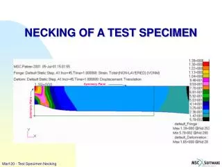
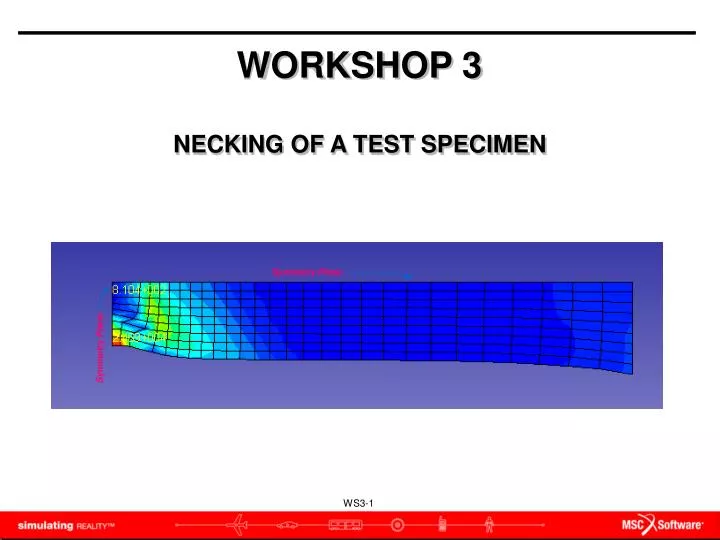
Symmetry Plane Symmetry Plane WORKSHOP 3 NECKING OF A TEST SPECIMEN
Model Description • In this lesson, you will stretch an 8 inch long planar steel bar by 1.65 inch (i.e. more than 20% of its length). This elastic-plastic problem will demonstrate the importance of the concept of true stress (or Cauchy stress) in non-linear analysis. This test specimen will be modeled using a quarter symmetry model.
Objective • Large Deflections/Strains analysis • Elastic-Plastic material model using isotropic hardening • Required • A file named necking.bdf in your working directory (Ask your instructor for it if you don’t see it before starting) • Proceed to the next page.
Suggested Steps for Exercise: • Import the meshed model (necking.bdf)to SimXpert • Set MAT1 & MATTEP material cards • Set Plane stress elements for this model • Fix the vertical and horizontal lines of symmetry of the bar and pull the other end by 1.65 inches. • Create a Sol600 job
Step 1. Open a New Database a b Open a new database , Structures Workspace. • Launch SimXpert. • Select Structures.
a b c d f e Step 2. Set Unit Set the units to English. • Select Tools / Options • Select Units Manager. • Click Standard Units. • Select the line containing English Units (in, lb, s…) • Click OK • Click OK.
Step 3. Import the necking.bdf b c a Import the required geometry. • Select File / Import / Nastran • Select necking.bdf as the File name. • Click Apply. In order to use Plain Strain 2D Solid elements, the geometry must be in the X-Y Plane at Z=0. The normals of the elements must point in the +Z Direction.
Step 4. Input the Stress vs. Strain Curve Define the Plastic Strain vs. Stress Curve. • In Materials and Properties tab, select Table \ StructPhysical \ Stress-Strain. • Enter Stress-Strain_1 as Table name • Click + icon to add rows • Key in all data as we provide • Click OK a b c d e
Step 5. Define Plastic Material Modify the material aluminum with elastic properties. • In Model Brower, double click Material / Aluminum • Click Advanced icon. • Click Add Constitutive Model / Elasto Plastic. b a c
Step 5. Define Plastic Material (cont.) Create the material aluminum_1100, with elastic properties. • Select Nonlinear Data Input: Stress-Strain Data. • Stress-Strain Data: select the Stress-Strain_1 curve which you created in step16. • Click OK. d e f
Step 6. Define the Element Properties-convert to plane stress a Convert plane strain elements to plane stress. • On the LBC’s tab, select PARAM from the Parameter group • Enter MREL1103 in N filed • Enter 3 in V1 field • Click Create. c b d This step is for SOL600 to set plane stress element property. For more info, please check Nastran qrg document.
a Step 7. LBC: symmetric_vertical Create the three required Displacement Boundary Conditions. Here we create symmetric_vertical. • On LBC’s tab, select General from the Constraint group • Enter symmetry_vertical as Name. • Check only Tx • Pick nodes along the symmetric edge • Click Apply b d c e
Step 8. LBC: pull_at_end Create the pull_at_end Displacement Boundary Conditions. • Enter pull_at_end as Name. • Check Tx and enter 1.65 • Check Ty and enter 0 • Pick nodes along the right edge • Click Apply a d b c e
Step 9. LBC: symmetric_horiz Create the symmetric_horiz Displacement Boundary Conditions. • Enter symmetric_horiz as the New Set Name. • Check only Ty • Pick nodes along the upper edge • Click OK a c b d
Step 10. Display LBC Change display mode: Request plotting of Loads/BCs markers on FEM entities. • Click Render On/Off to show LBCs a
Step 11. Create a New Job Create a new job. • Right-click FileSet and select Create new Nastran Job • Enter Necking for the Job Name. • Select Implicit Nonlinear Analysis (SOL 600) for the Solution Type. • Click the ellipses on the Solver Input file. • Select the file path • Enter Necking for the File Name.. • Click OK.. a c b c d e
Step 12. Select Load/BCs Select Load/BCs. • In Model Browser, right click Simulation / Necking / Load Cases / DefaultLoadCase / Load/Boundaries / Select Lbc Set • Select DufaultLbcSet • Click OK.. b c a
Step 13. Subcase Properties Subcase Properties • Open Model Browser, double click Necking \ Load Cases \ Loadcase Control • Check on DefineLoadIncrementParameters option • Switch Increment Type from Fixed to Adaptive • Enter Trial Time Step Size as 0.01 • Enter 1 as Total Time. • Click on Apply b c d e a f
Step 13. Subcase Properties (cont.) Subcase Properties • Switch to Sol600SubcaseIterationParameters dialog • Enter 0.01 as in Residual Tolerances / Relative Residual Force • Click Apply. a b c d
Step 13. Subcase Properties (cont.) Setup the Analysis Parameter • Select SOL600SubcaseNonlinearGeomParameter dialog • Switch Nonlinear Geometric Effects option to Large Displacement/Large Strains • Click Apply • Click Close a b c d e
Step 14. Output Requests-Element Results • Right Click on Output Requests to add the following outputTotal Strain Tensor(301) Plastic Strain Tensor (321) Cauchy Stress Tensor (341) a
Step 15. Run this job Run this job • Open Model Browser, click right mouse button at Necking,Select Run. a
Step 16. Attach result file Attach results files, *.t16 • File \ Attach Results\ Result Entities… • Choose necking.marc.t16 • Click OK b a c
Step 17. Plot the Deformation Results a c b d e Plot the deformation & stress results. • On the Results tab, select Deformation • Result Cases: select the Increment with Time=1.0 • Result type: Displacement, Translation • Click Display setting tab, change Deformed display scaling to “True :1”. • Choose Update
Step 21. Plot the Stress Results a e d c b Plot the deformation & stress results. • Plot type: Fringe • Result Cases: select the Increment with Time=1.0 • Result type: Result Type: Stress,Cauchy • Derivation: von Mises • Choose Update