Download
1 / 71
730 likes | 1.34k Views
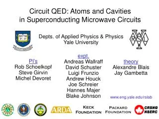
Overview on Microwave Circuits Design. Prof. Yongchae Jeong (E-mail: ycjeong@chonbuk.ac.kr). Overview on Microwave Circuits Design. 1. Electronics 2. Radio Wave 3. Comparison between Analog, Digital and Microwave, 4. Microwave Applications

E N D
Overview on Microwave Circuits Design Prof. Yongchae Jeong (E-mail: ycjeong@chonbuk.ac.kr)
Overview on Microwave Circuits Design 1. Electronics 2. Radio Wave 3. Comparison between Analog, Digital andMicrowave, 4. Microwave Applications 5. Measurement Systems for Microwave Circuits 6. Curriculum for Microwave Engineering 7. Basic Concepts in Microwave Circuit Design 8. RF Transceiver Architectures
1. Electronics -어원: Electronics= Electron (전자)+ics (학문명 접미사) -정의 1 : 진공 속이나 기체, 고체 내에서의 전자의 운동을 연구하는 학문 및 그것을 이용하는 기술 -정의 2 : 전자기술의 다방면에 걸친 발전과 그 두드러진 유용성으로 인해 생긴 개념으로 초기에는 진공 또는 기체 속에서 이루어지는 전자 운동의 이용을 초점으로 하는 것이었으나, 1948년 미국 벨 연구소에서 개발한 트랜지스터에 의해서 질적으로 변화하여 반도체내의 전자의 운동을 이용하는 이론과 기술이 전자공학의 주류로 변화 -기술적 특징: 빛, 열, 음, 전자파 등을 전기 신호화해서 전송하고 처리 -고체 전자공학(반도체)의 발전 과정 Diode(진공관 다이오드, 반도체 다이오드) Transistor(트랜지스터) IC(Integrated Circuit: 집적회로) VLSI(Very Large Scale Intefration:초대규모 집적회로) Digital IC Analog IC, RFIC(Radio Frequency IC), MMIC(Monolithic Microwave IC) OEIC (Optoelectronic IC)
1. Electronics 그림 1. 전자 공학의 흐름도
2. Radio Wave -Radio Wave -인공적인 매개물이 없이 공간에 전파하는 3THz 보다 낮은 주파수의 전자파 -무선통신에 사용되는 무선 주파수를 포함하여 적외선, 가시광선, 자외선, X선, 우주선 등을 총칭 -전파의 사용 범위는 대체로 3kHz ~ 3THz 의 주파수를 갖는 전자파 -무선통신, 라디오 방송, TV 방송, 무선 항해, 레이더 등은 모두 전파를 이용하는 것으로, 전파가 점유하는 주파수 범위는 매우 넓고 주파수에 따라 파장이나 전파되는 특성이 다르며, 현재 국제 전기 통신 협약과 전파법에 의해 관리, 이용되고 있는 것은 일부분에 불과 그림 2. 전자파의 예
2. Radio Wave 전파의 성질 1)전파의 직진 : 동일 매개체를 통과할 경우에 직진하는데 주파수가 높을수록 직진성이 강함 2) 전파의 반사 및 굴절 : 빛이 물속을 통과할 때처럼 전파 또한 다른 물질로 구성된 매개체를 통과할 경우에는 그 물질의 경계면에서 일부는 반사되고 일부는 진행방향이 변하여 투과되면서 굴절 3) 전파의 회절 :전자파는 빛과 마찬가지로 전파 경로상에 산악 또는 건물 등과 같은 장애물이 있는 경우, 그 뒤쪽에서 전파의 일부가 휘어져 수신 4) 전파의 간섭 ① 시간차에 의한 간섭 : 동일 기지국에서 방사된 동일한 주파수가 여러 경로를 거치면서 전파의 도달 시간에 차이가 생겨 발생 ②인접 채널 간섭 : 서로 다른 기지국으로부터 발사되는 동일한 주파수로 인해 일어나는 간섭 ③동일 채널 간섭 : 여러 단말기가 동시에 통화시도를 하면 같은 채널을 사용하게 되는데, 이때 반대쪽에서 나는 간섭
2. Radio Wave 그림 3. 전파의 전파 경로
2. Radio Wave RF의 정의 -RF (Radio Frequency) : 방사 ( 방파 ) 주파수 • 전자파를 이용한 무선장비의 소자 및 시스템 • RF : 1GHz • 사전적 의미 • Microwave : 300MHz ~ 300GHz - 대략 100 ~300MHz 이상의 고주파 무선통신 및 고주파를 이용하는 소자, 부품, 시스템, 관련 장비 분야.
2. Radio Wave 주파수(Frequency)의 정의 • 전자파가 움직이는 보이지 않는 길(지정된 주파수를 통하여 정보를 교환) ⇒ 파장 또 진동수를 기준으로 한 약속 • 1초 동안에 일정한 주기로 진동하는 횟수 [Hz] • 그림 4. 주파수의 개념
2. Radio Wave *상업적인 RF 대역 표 1. 무선 주파수 대역
2. Radio Wave *Microwave 대역 표 2. Microwave 대역
3. Comparison between Analog, Microwave, Digital 그림 5. Analog 와 Digital
4. Microwave Applications 무선 및 이동 통신에서의 RF [Super Heterodyne 방식] 그림 6. Super heterodyne 형태의 AM 수신기의 기본적인 요소 Super Heterodyne 방식 : 수신기의 감도를 높이기 위해서 고주파 증폭기의 이득을 크게 한다는 것에 한도가 있으므로, 고주파 신호를 한번 주파수가 낮은 증간 주파수로 변환시켜 이것을 증폭한 후에 복조하여 저주파 증폭을 하는 방식으로 회로가 복잡하고 가격이 비싸지만, 감도와 선택도가 향상되고 광대역에 걸쳐 주파수 충실도가 우월 Direct Conversion (Zero IF) 방식 : IF를 사용하지 않으므로 채널의 선택도와 감도가 떨어지긴 하지만, IF단을 사용하지 않기 때문에 가격면에서 저가이고 공간을 절약할 수 있으므로 작고 가벼움. IF (Intermediate Frequency) : 주파수변환기에 의해 수신 전파의 주파수와 국부 발진기 주파수 차에 해당하는 주파수(수신측), 일반적으로 중간 주파수는 수신 주파수보다 낮게 하여 증폭하기 쉽고 선택도 및 충실도를 높게 하는 것
4. Microwave Applications 일반적인 시스템 구조
4. Microwave Applications DirectConversion 방식
4. Microwave Applications Super Heterodyne 방식
4. Microwave Applications • RF 와 Microwave를 사용하는 이유 • 고주파에서 더 넓은 대역으로 전달 (정보 운반 능력) • 작아지는 시스템에 따르는 소자의 크기 문제 • 동작에 있어 높은 속도를 요구 • 안테나 이득은 안테나의 전기적인 크기에 비례 • 작은 파장에 따른 안테나의 길이 문제 해결 • 신호가 전리층에서 튀지 않으므로 지상과 위성과의 통신이 가능
4. Microwave Applications *RF 응용분야 표 3. RF 응용분야
5. Measurement Systems for Microwave Engineering Network Analyzer: 하나의 기계 안에 주파수Source와 Spectrum Analyzer가 들어있어서, 입력과 출력의 주파수 신호분포결과를 서로 나눔으로써 S 파라미터를 측정하는 장비 그림7. 8510C Network Analyzer Systems, 45 MHz to 110 GHz
5. Measurement Systems for Microwave Engineering Scalar Network Analyzer : magnitude Vector Network Analyzer : magnitude, phase time domain frequency domain Linear Device만측정가능(Frequency Doubler, Mixer등은측정불가능) DelayReflection 측정 (1 port device) SWR S-parameter(S11, S22) Reflection Coefficient Impedance Return Loss Transmission 측정 (2 port device) Gain or Insertion Loss S-parameter(S11, S22) Transmission Coefficient Insertion Phase Group Delay
5. Measurement Systems for Microwave Engineering Spectrum Analyzer: 1-port 측정장비로계측기입력단에서 어느 주파수성분이감지되는지를표시하는장비,Phase Noise도 측정. 그림8. 8563EC Portable Spectrum Analyzer, 9 kHz to 25.6 GHz
5. Measurement Systems for Microwave Engineering Noise Figure Meter (or Analyzer): 잡음을임의로발생시키는Noise Source와잡음지수를측정하는Noise Figure meter 로구성, 회로와수신부시스템의잡음지수를측정,Tuner를사용하여Noise Figure Parameter를추출가능, 저잡음증폭기의잡음지수연구와수신부의잡음지수측정에필수적인장비 그림9. N8975A Series Noise Figure Analyzer
5. Measurement Systems for Microwave Engineering Power Meter: Power 측정 그림10. E4418B Single-Channel Power Meter
5. Measurement Systems for Microwave Engineering Probe Station: Wafer 및Chip sample등전자소자들의전자, 전기적특성및물성연구에주로사용하는소자탐침용장비. 주로I-V, C-V, 각종 파라미터및Wafer의신뢰성을테스트 그림11. Cascade Microtech Probe System
6. Curriculum for Microwave Engineering 전자기학(Electromagnetics): Vector 및scalar, 정전계, 유전체의정전용량, 자성체와인덕턴스, 정자계의특성을익히고시변계에서Maxwell 방정식을통해기본적인전자기적현상을이해 회로이론(Circuit Theory): 키르히호프법칙, RLC 응답, Laplace 변환, Fourier변환등의여러회로이론들에대한이해 물리전자(Solid State Electronic Device): 반도체소자의특성과동작의원리, 다이오드와트랜지스터의이해 전자회로(Electronic Circuit): 다이오드,바이폴라트랜지스터, FET와같은전자소자의동작원리를습득하며, 이들의소신호모델을이용한증폭회로의해석과설계기법을학습 초고주파공학(Microwave Engineering): 전송선이론, 초고주파회로망분석, 정합이론및각종초고주파소자및증폭기에대한이해 무선통신회로 및 실험(Wireless Communication Circuits and Experiments): 무선통신시스템의 구성하고 있는 주요 회로의 동작 및 설계 방법을 학습 전파공학(Wave Propagation Engineering): 대기 중에서의 전파의 전파 과정과 안테나의 설계이론 학습
7. Basic Concepts in Microwave Circuit Design Memoryless system A system is called “memoryless” if its output does not depend on the past values of its input. For memoryless linear system, y(t)=x(t) where is a function of time if the system is time variant For a memoryless nonlinear system, the input-output relationship can be approximated with a polynomial, where j are in general functions of time if the system is time invariant For memoryless and time-variant systems,
7. Basic Concepts in Microwave Circuit Design • Harmonics If a sinusoid is applied to a nonlinear system, the output generally exhibits frequency components that are integer multiples of the input frequency. • if x(t)=Acost, then • where the input frequency (): “fundamental” • the higher-order terms(n, n:integer): “harmonics.” • Even-order harmonics result from j with even j and vanish if the system has • odd symmetry, i.e., if it is fully differential. • The amplitude of the nth harmonic consists of a term proportional to An and • other terms proportional to higher powers of A.
7. Basic Concepts in Microwave Circuit Design Gain Compression The small signal gain (1)of circuit is usually obtained with the assumption that harmonics are negligible. In most circuits of interest, the output is a “compressive” or “saturating” function of input. At high input level, gain is a decreasing function of A.
7. Basic Concepts in Microwave Circuit Design 1-dB compression point(P1dB): The input signal level that causes the small signal gain to drop by 1dB. Fig. 7 Definition of 1dB compression point To calculate the 1-dB compression point,
7. Basic Concepts in Microwave Circuit Design Desensitization and blocking When the desired signal is fed to circuit with a strong interferer, the “average” gain of the circuit is reduced because of a large interferer : “desensitization”
7. Basic Concepts in Microwave Circuit Design For A1 << A2, For 3<0 and sufficiently large A2, the overall gain drops zero, and we say the signal is “blocked” in RF design. Many RF receivers must be able to withstand blocking signals 60 to 70dB greater than the wanted signal. Filter, Matching circuits, etc.
7. Basic Concepts in Microwave Circuit Design Cross Modulation When a weak signal and a strong interferer pass through a nonlinear system, the transfer of modulation on the amplitude of the the interferer to the amplitude of the weak signal is occurred. The desired signal at the output contains amplitude modulation at m and 2m.
7. Basic Concepts in Microwave Circuit Design Intermodulaton When two signals with different frequencies are applied to a nonlinear system, the output in general exhibits some components that are not harmonics of the input frequencies. Intermodulation distortion(IMD) Fundamental components Intermodulation products:
7. Basic Concepts in Microwave Circuit Design The interest IM products are the third-order IM products at 22-1 and 21-2. If the difference between 1 and 2 is small, the components at 21-2 and 22-1 appear in the vicinity of 1 and 2 . Fig. 8 Intermodulation in a nonlinear system If a weak signal accompanied by two strong interferers experiences third- order nonlinearity, then one of the IM products falls in the band of interest, corrupting the desired component. Fig. 9 Corruption of a signal due to intermodulation between two interferers
7. Basic Concepts in Microwave Circuit Design IP3 This parameter is measured by a two-tone test in which A is chosen to be sufficiently small so that higher-order nonlinear terms are negligible and the gain is relatively constant and equal to 1. As A increases, the fundamentals increase in proportion to A, whereas the third-order IM products increase in proportion to A3. Fig. 10 Growth of output components in an intermodulation test Horizontal coordinate : Input IP3(“IIP3”) Vertical coordinate: Output IP3(“OIP3”) IP3 is used as a measure of linearity and a unique quantity that by itself can serves as a means of comparing the linearity of different circuits.
7. Basic Concepts in Microwave Circuit Design Fig. 11 (a)Calculation of IP3 without extrapolation, (b)graphical interpretation of (a) The actual value of IP3, however, must still be obtained through accurate extrapolation to ensure that all nonlinear and frequency-dependent effects are taken into account.
7. Basic Concepts in Microwave Circuit Design Calculation of an overall input third intercept point in terms of the IP3 and gain of the individual stage. Two nonlinear stages in cascade Fig. 12 Cascaded nonlinear stages The overall OIP3:
7. Basic Concepts in Microwave Circuit Design The alternate overall OIP3: where AIP3,1 and AIP3,2 represent the input IP3 points of the 1st and 2nd stages. From the result, 1 increases, the overall IP3 decreases. This is because with higher gain in the first stage, the second stage senses larger input levels producing greater IM3 products.
7. Basic Concepts in Microwave Circuit Design Noise Thermal noise (or Johnson noise, Nyquist noise) - The agitated charge carrier random motion noise being caused by thermal vibration of bound charge - White noise up to 1013 Hz - Noise power: P=kTB where k: Boltzman constant (1.3810-23 J/ºK) T: Absolute temperature B: System bandwidth Ex.]The available power in a 1Hz bandwidth from a thermal noise source P=kT=410-23 [W/Hz]=-174dBm/Hz @room temperature Shot noise (or Schottky noise) - The transfer noise of charge across an energy barrier (ex. A PN junction, IDS in MOSFET) - where q=1.6 10-19[C] (electron charge), Idc:dc current through the device