Download
1 / 14
140 likes | 159 Views
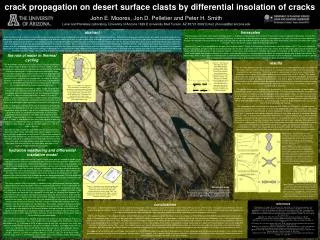
On calibration of micro-crack model of thermally induced cracks through inverse analysis. Dr Vladimir Buljak University of Belgrade, Faculty of Mechanical Engineering, Department of Strength of materials. 2 nd International Conference and Expo On Ceramics and Composite materials

E N D
On calibration of micro-crack model of thermally induced cracks through inverse analysis Dr Vladimir Buljak University of Belgrade, Faculty of Mechanical Engineering, Department of Strength of materials 2nd International Conference and Expo On Ceramics and Composite materials Berlin, 25-26 July 2016. New ceramic technologies and novel multifunctional ceramic devices and structures
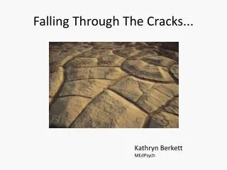
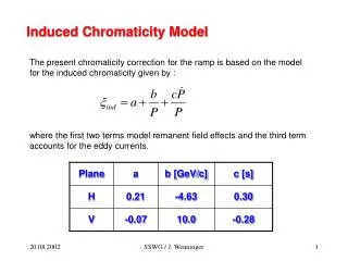
dr Vladimir Buljak Micro-cracking generated by cooling of polycrystalline ceramics -T α1 α2 Bruno G, Katchanov M / Journal of European Ceramic Society 33, 2013.
dr Vladimir Buljak Cohesive elements for crack opening simulations + Easy numerical implementation - Crack path is a priori fixed (i.e. mesh dependant solution)
dr Vladimir Buljak FEM model for representative volume unit • Adopted model specifications: • Grain behavior elastic and isotropic the same for all grains • Thermal expansion is anisotropic and different for each grain • Cohesive zone modeled by traction separation law governed by 2 parameters
dr Vladimir Buljak FEM model for representative volume unit Coupled thermo-mechanical analysis with cooling down phase
dr Vladimir Buljak The use of developed FEM for elastic modulus hysteresis prediction Drop in elastic modulus value during cooling Experimentally measured quantities Computed quantities Thermo mechanically coupled FEM Linear elastic steps performed using the same FEM ET1 ET2 ET3 ET4 …
dr Vladimir Buljak Parameter calibration through inverse analysis Direct operator Inputs Model Outputs Inverse operator Parameter identification Minimization of Objective Function (OF) Experimental data Uexp Calculated data Ucal
dr Vladimir Buljak Minimization of resulting objective function First order optimization algorithm (e.g. Trust Region) Initial guess for sought parameters (p1,p2,…,pn) Compute for the set of values (p1,p2,…,pn) Compute first derivatives with respect to each of the sought parameters pi by finite difference Evaluate values for parameters for the next iterate
dr Vladimir Buljak Results of IA calibration Problem description: • Parameters to identify: 14 thermal expansion coefficients, and 2 cohesive crack parameters • Cohesive behavior assumed the same for each grain boundary • Assumed isotropic elasticity with known constants • Measurable quantities: normalized curve of Young’s modulus versus temperature drop • Minimization problem solved by iterative trust region algorithm
dr Vladimir Buljak Results of IA calibration Assessed and experimental curve for Young’s modulus vs. temperature drop
dr Vladimir Buljak Evaluation of the influence in grain orientation Thermal expansion coefficients for Grain 1, 2, 3, … and cohesive crack parameters IA procedure
dr Vladimir Buljak Evaluation of the influence in grain orientation: IA results Assessed and experimental curve for Young’s modulus vs. temperature drop
dr Vladimir Buljak Conclusion and future prospects • Conclusions: • Proposed model with cohesive crack elements used for micro crack simulations can capture global behavior with decrease in Young’s modulus • Within relative small RVU the influence of grain orientation plays significant role in the transition range • Model posses a flexibility to take into account for more complex behavior e.g. anisotropy in elastic (unknown) properties, different cohesive models for different grain bounds etc. • Future prospects • Testing of grain size and orientation influence by using larger RVU • Extending the method to 3D samples • Development of continuum damage models to be use for larger scale calculations
Acknowledgments The research results referred to here have been achieved within European Union’s Seventh Framework Programme FP7/2007-2013/ under REA grand agreement number PITN-GA-2013-606878-CERMAT2 • THNAK YOU FOR • YOUR ATTENTION! vladimir.buljak@polimi.it