Download
1 / 10
100 likes | 212 Views
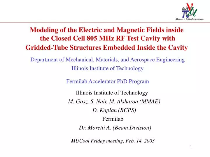
Modeling of the Electric and Magnetic Fields inside the Closed Cell 805 MHz RF Test Cavity with Gridded-Tube Structures Embedded Inside the Cavity. Department of Mechanical, Materials, and Aerospace Engineering Illinois Institute of Technology Fermilab Accelerator PhD Program.

E N D
Modeling of the Electric and Magnetic Fields inside the Closed Cell 805 MHz RF Test Cavity with Gridded-Tube Structures Embedded Inside the Cavity Department of Mechanical, Materials, and Aerospace Engineering Illinois Institute of Technology Fermilab Accelerator PhD Program Illinois Institute of Technology M. Gosz, S. Nair, M. Alsharoa (MMAE) D. Kaplan (BCPS) Fermilab Dr. Moretti A. (Beam Division) MUCool Friday meeting, Feb. 14, 2003
I. DESCRIPTION OF THE CLOSED CELL 805 MHZ TEST CAVITY • Design variables: • tube outer diameter, tube wall thickness • number of tubes and grids • grid spacing • type of coolant and coolant flow rate • grid configuration: • physically and electrically connected grids • or plane grid (waffle grid) Fig. 1 Cross-sectional view of the closed-cell 805 MHz test cavity • The cavity model contains a Be-window from one side and a gridded-tube structure from the other side that was built in place of the other Be- window at the same location. • To reduce the computation time, quarter of cavity is considered, and the tubes are represented as solid cylinders for the modal analysis for solving for E and H fields.
R/6 R/3 R/3 R/6 R II. SIX BY SIX REGULAR GRID Fig.3: Description of the six by six regular grid ANSYS model Fig. 2: Description of the six by six regular grid • The following cases are considered: • Tube Diameter: 1.00 cm • Tube Diameter: 1.25 cm • Tube Diameter: 1.50 cm • Grid Configuration: “Waffle” grid
A. SIX BY SIX REGULAR GRID WITH 1.0 cm TUBE DIAMETER Tube surface electric filed enhancement = 1.64 Fig. 4 Contour plot of the magnitude of the electric field Fig. 5 Contour plot of the magnitude of the magnetic field
B. SIX BY SIX REGULAR GRID WITH 1.25 cm TUBE DIAMETER Tube surface electric filed enhancement = 1.40 Fig. 6 Contour plot of the magnitude of the electric field Fig. 7 Contour plot of the magnitude of the magnetic field
C. SIX BY SIX REGULAR GRID WITH 1.5 cm TUBE DIAMETER Tube surface electric filed enhancement = 1.39 Fig. 8 Contour plot of the magnitude of the electric field Fig. 9 Contour plot of the magnitude of the magnetic field
R/10 3R/5 R/5 R/10 R III. SIX BY SIX MIDDLE-CONCENTRATED GRID Fig. 11 Description of the six by six middle- concentrated grid ANSYS model Fig. 10 Description of the six by six middle- concentrated grid • Grid Configuration: Waffle • Tube Outer diameter: 1.0 cm
Tube surface electric filed enhancement = 1.40 Fig. 12 Contour plot of the magnitude of the electric field Fig. 13 Contour plot of the magnitude of the magnetic field
Tube DIA (cm) Grid 0.50 1.00 1.25 1.50 4*4 Regular Connected 3.60 4*4 Regular Waffle 2.30 1.80 6*6 Regular Waffle 1.64 1.40 1.39 6*6 Middle-Concentrated Waffle 1.40 IV. SUMMARY OF THE RESULTS OF TUBE SURFACE ELECTRIC FIELD ENHANCEMENT Table 1: Summary of the results of tube surface electric field enhancement for the cases that have been considered
V. CONCLUSION • Increasing tube outer diameter, using waffle grid and increasing number of tubes reduces tube surface field enhancement for 2*2, 4*4 and 6*6 waffle grids. Complete analysis and optimization are needed ! VI. PRESENT AND FUTURE WORK • Modal electric and magnetic fields analysis of the 805 MHz cavity with different configurations of gridded-tube structures embedded inside the cavity; “8*8 Connected grids, 8*8 Waffle grid, Change in tube outer diameter and Change in grid spacing. Do you have any other configurations ?” Note: Increasing number of tubes and tube outer diameter reduces tube surface electric field enhancement and enhances heat transfer. How far those can be increased ? • Calculating the heat flux loads on the gridded-tube structures and performing thermal stress analysis. • PhD thesis proposal is under review by the MMAE team – IIT. Using non-linear optimization techniques to optimize the design parameters of the gridded-tube structure has been proposed.