Download
1 / 26
260 likes | 339 Views
OUTCOMES OF THE LRFF (LHC RF FINGERS) TASK FORCE IN 2012.

E N D
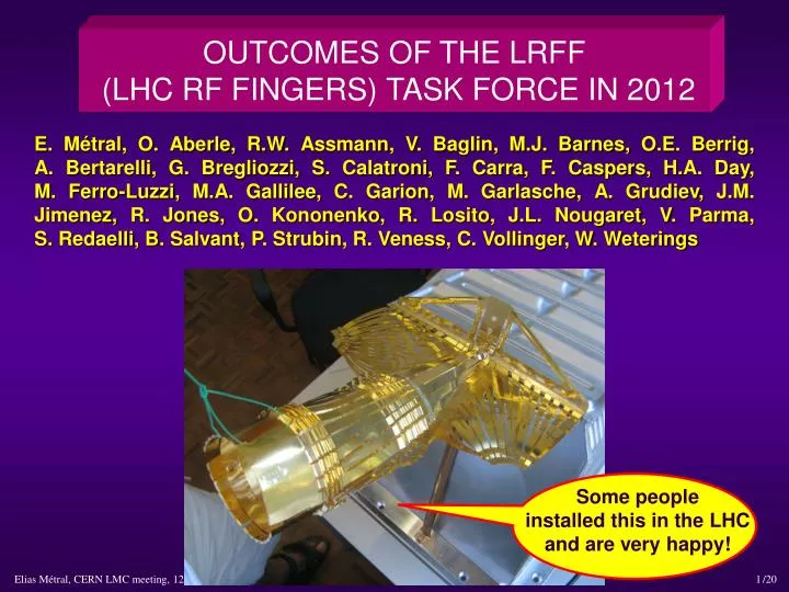
OUTCOMES OF THE LRFF (LHC RF FINGERS) TASK FORCE IN 2012 E. Métral, O. Aberle, R.W. Assmann, V. Baglin, M.J. Barnes, O.E. Berrig, A. Bertarelli, G. Bregliozzi, S. Calatroni, F. Carra, F. Caspers, H.A. Day, M. Ferro-Luzzi, M.A. Gallilee, C. Garion, M. Garlasche, A. Grudiev, J.M. Jimenez, R. Jones, O. Kononenko, R. Losito, J.L. Nougaret, V. Parma, S. Redaelli, B. Salvant, P. Strubin, R. Veness, C. Vollinger, W. Weterings Some people installed this in the LHC and are very happy!
OUTLINE (for 15 min) • Introduction • Why do we need RF fingers and/or ferrite (absorbers)? • Several designs for RF fingers • Possible issues to consider with RF fingers • Typical nonconformities in warm modules found with X-rays • Conclusions and recommendations • Appendix 1: List of all the (92) nonconformities • Appendix 2: VMTSA found with defects in 2011 (8 bellows out of 20) • Appendix 3: “Ideal” outline
INTRODUCTION (1/3) • Beam-induced heating has been observed in several LHC components during the 2011 run when the bunch/beam intensity was increased and/or the bunch length reduced • In particular 8 bellows, out of the 10 double-bellows modules (called VMTSA) present in the machine, were found with the spring, which should keep the RF fingers in good electrical contact with the central insert, broken • SS spring deformed and brazed to the CuBe RF fingers with RF fingers permanently deformed => Estimated temp. of ~ 800 - 1000 °C From X-rays
INTRODUCTION (2/3) • Proposition made during the LMC meeting # 119 (18/01/2012) to review the design of all the components of the LHC equipped with RF fingers => LRFF (LHC RF Fingers) Task Force before LS1 • Web site: http://emetral.web.cern.ch/emetral/LRFF/LRFF.htm • 1st (kick-off) meeting: 20/03/2012 • 20th (last) meeting: 27/11/2012 • Members
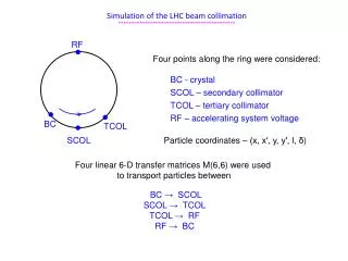
INTRODUCTION (3/3) • Mandate • Review the design of all components of the LHC equipped with RF fingers, evaluate the compatibility with ultimate (and HL-LHC) bunch populations (i.e. up to 2.2E11 p/b for the 25 ns beam and 3.5E11 p/b for the 50 ns beam) and (rms) bunch lengths (i.e. 7.5 cm but also ~ 4 cm which could be an option) regarding impedance and HOM screening and provide a list of maximum bunch currents, acceptable bunch lengths etc. • Evaluate all associated mitigation solutions like ferrite absorbers and their collateral effects, in particular the induced heating and resulting outgassing • Make proposals of design changes and/or mitigation measures for each configuration depending on its criticality for beam operation • Approve functional specifications for all equipments by the end of the year (2012)
WHY DO WE NEED RF FINGERS AND/OR FERRITE? (1/5) • To avoid having too large impedances (longitudinal or transverse) due to (big) changes of geometry for moving equipments, which can lead to • Beam-induced RF heating (if real part of longitudinal impedance) • Longitudinal or transverse beam instabilities (if real and/or imaginary parts of longitudinal or transverse impedances) • Example of RF fingers: • PIMs = Plug-In Modules • Example of ferrite tiles: • Installed in the new VMTSA • in 2012 Initial dimensions (quickly available!): ~ 12 cm × 3 cm × 1 cm
WHY DO WE NEED RF FINGERS AND/OR FERRITE? (2/5) • Example for the RF heating => Consider the case of a narrow resonance (trapped mode due to the geometry) => 3 parameters (obtained from EM simulations): • Resonance frequency => Assumed to be here fr = 1 GHz • Shunt impedance => Assumed to be here Rl = 10 Ω • Quality factor Q=> Scanned below HWHH = Half Width at Half Height = fr/ (2 Q) Typically between few 102 and few 103 Rl Coupled-bunch lines • Re(Zl) [Ω] • Re(Zl) [Ω] Q = 100 Q = 20 fr
WHY DO WE NEED RF FINGERS AND/OR FERRITE? (3/5) • Power loss formula for the case of a (sharp) resonance (i.e. with only 1 line) PdB ( fr ) is the power in dB read from a power spectrum (computed or measured) at the frequency fr Total beam current: M = # bunches Ib = Nbe f0 ~ 1 for HL-LHC Typically below few 10s of kΩ (between few 100s Ω and few kΩ)
WHY DO WE NEED RF FINGERS AND/OR FERRITE? (4/5) • Consider the following (analytical) distribution Computed PdB ( f) 5kΩ gives 1 W at 1.4 GHz
WHY DO WE NEED RF FINGERS AND/OR FERRITE? (5/5) Assuming the same shape of the profile
SEVERAL DESIGNS FOR RF FINGERS (1/3) • 1) Funnel for the PIMs • For case of longitudinal movement (only) • Good for contact / gap • Possible issue with buckling and aperture restriction Funnel RF contact fingers to shield the distorted geometry of the bellows from the beam Spring (to be put at the extremity of the RF fingers where there is a groove) Conforming RF fingers • 2) Spring for the VMTSA • For case of transversal movement • Possible issue with contact / gap (due to elliptical shape) => RF heating • Possible issue with aperture restriction Big gap created in case the spring is NOT in place
SEVERAL DESIGNS FOR RF FINGERS (2/3) • 3) Fixed extremities for the LHCb VELO (VErtexLOcator) • Seems to work very well! • Well-studied VELO design in terms of impedance effects paid off => No issue observed • Future upgrade: Reduction of the inner radius of the foil (from 5.5 to 3 − 4 mm) • 4) New RF design from TE/VSC • 1st prototype based on 2 convolutions manufactured this year. Tests ongoing • Issue: Imaginary part of the longitudinal impedance (if many and not elongated) Device EM longer than mechanically due to induced current having to follow the convolutions
SEVERAL DESIGNS FOR RF FINGERS (3/3) • 5) Longitudinal sliding contacts for collimators • Initial proposal for 1st (SPS) prototype (2003) • Uncoated CuBe fingers sliding on C/C • Electrical contact resistance ~ 30 mΩ (specification: 1 mΩ) => Redesign necessary Solution to the pb observed with the TCDD
POSSIBLE ISSUES TO CONSIDER WITH RF FINGERS • RF fingers for PIMs • Low contact resistance < 0.1 mΩ (i.e. 3 mΩ / RF finger as there are 30 RF fingers in //) • No cold welding • Low friction • Good formability properties • RF fingers for collimators • Same as above with contact resistance < 1 mΩ • Resistance to bake out: 250°C / 1000 h • Resistance to heating => Good thermal conductivity • Wear after many cycles “open-close of the jaws” (1500 cycles ~ 4 years) • Good electric contacts requires • Low surface roughness • Soft metals (at least one) • No oxide layer at the surface
TYPICAL NONCONFORMITIES IN WARM MODULES FOUND WITH X-RAYS (1/2) • 1800 X-rays taken • 92 NC (~ 5 %) => 2 types of design: circular and elliptical (VMTSA) • 58 vacuum sectors concerned out of 190 at room temperature (88 sectors at cryogenic temperature) CONFORMITY
TYPICAL NONCONFORMITIES IN WARM MODULES FOUND WITH X-RAYS (2/2) NONCONFORMITIES
CONCLUSIONS AND RECOMMENDATIONS (1/3) • A lot of experience has been accumulated at CERN over the past decades for the use of RF fingers and/or ferrite absorbers • This experience needs to be (and will be) summarized in a forthcoming internal report • Guidelines for the use of RF fingers • Guidelines for the use of ferrite absorbers => Nominated “ferrite responsible persons” at CERN: Fritz Caspers and Christine Vollinger • Several designs of RF fingers are used in the LHC depending on the requirements • Some have been studied in great detail • => Takes time but it paid off! • New design from TE/VSC under careful checks
CONCLUSIONS AND RECOMMENDATIONS (2/3) • VMTSA issues observed in 2011 have been reproduced by simulations and traced back to be due to a gap between some RF fingers and central insert • The spring acted as a fuse => Robust mechanical design needed • No issue at all this year => Our modifications during last year Xmas break’s crash program were sufficient to assure a good contact • All the VMTSA modules will be removed during LS1 • Full list of the 92 nonconformities revealed in warm modules after X-rays campaign => Should be repaired during LS1 • For the cases studied, we didn’t see any problem with impedance for conforming RF fingers => No (big) pb expected for HL-LHC bunch populations (i.e. up to 2.2E11 p/b for the 25 ns beam and 3.5E11 p/b for the 50 ns beam) • => Top priority for the future: Robust mechanical design to keep the contacts of all the RF fingers (e.g. with funnel as for the PIMs, or fixed extremities) + Very careful installation
CONCLUSIONS AND RECOMMENDATIONS (3/3) • BUT the big problem is the possible very short bunch of ~ 4 cm • 2012 run made with ~ 10 cm rms bunch length • Nominal (rms) bunch length = 7.5 cm (for both LHC and HL-LHC) and ~ 4 cm was also considered for HL-LHC => Needs many careful checks!! Assuming the same shape of the profile 5kΩ gave 1 W at 1.4 GHz for 9 cm => Becomes ~ 2 kW for 4.5 cm
APPENDIX 2: VMTSA FOUND WITH DEFECTS IN 2011 => 10 modules (each of 2 bellows) in total in 2011. 8 bellows were found with defects (see arrows below)
APPENDIX 3: “IDEAL” OUTLINE (1/2) But no time in 15 min • Introduction • Why do we need RF fingers and/or ferrite (absorbers)? • What we planned to do • What was done • RF fingers • Several designs • Possible issues to consider • Example of a known issue with a TCDD • Typical nonconformities found with X-rays • List of all the nonconformities • Recent issues observed with RF contacts in SPS • Guidelines
APPENDIX 3: “IDEAL” OUTLINE (2/2) But no time in 15 min • Ferrite absorbers • Several types, criteria and guidelines • Measurements of the EM properties • Figure of merit and design guidelines for the ferrite heating • Measurements of the vacuum properties • Pros and cons of RF fingers and ferrite absorbers • What was wrong with the PIMs in the cold part of LHC? • Follow-up of VMTSA issues in 2011 • Conclusions and recommendations => See last meeting of the LRFF TF: http://emetral.web.cern.ch/emetral/LRFF/20thMeeting_27-11-12/LRFF_EM_03-12-12_AfterMeetingComments_Final.pptx(76 slides) => See yesterday’s summary at TE-TM: http://emetral.web.cern.ch/emetral/LRFF/SummaryAtTE-TM_11-12-12/LRFF_EM_11-12-12_TE-TM.pptx(55 slides)