Download
1 / 26
260 likes | 265 Views
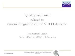
LHC b and its VE rtex LO cator integration into the LHC. Overview of LHC b Current VELO design: Mechanics Cooling system for Si detectors Vacuum issues RF issues Road map Summary and outlook. B 0 - D *+ . D 0 +. Typical event for LHC b. Generated polar

E N D
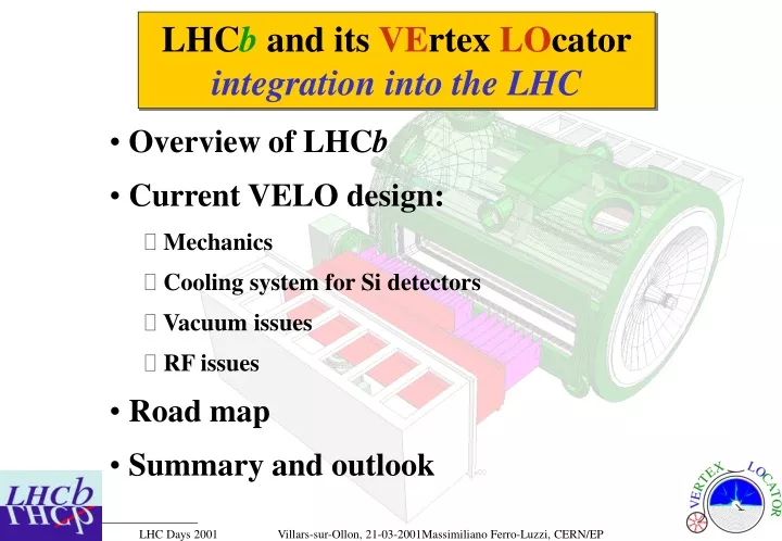
LHCband its VErtex LOcatorintegration into the LHC • Overview of LHCb • Current VELO design: • Mechanics • Cooling system for Si detectors • Vacuum issues • RF issues • Road map • Summary and outlook
B0 -D*+ D0 + Typical event for LHCb Generated polar angles of b and b hadrons (with PYTHIA) Primary vertex B0 +- 10 mm • LHCb: identify B-mesons and their age at decay • Crucial information: particle ID, 1ary and 2ary vertices • vertex detector used in trigger level-1 • offline decay distance resolution 120 m • (proper decay time resolution 0.04 ps)
LHCb Detector • Acceptance: • q=10...300mrad • Bakeable NEG-coated • beam pipe • Subsystems can • be retracted from • conical beam pipe • Warm dipole: • - B dz 4 Tm • - correction scheme • - ramp with LHC • - reverse polarity displaced IP8 “original” IP8
towards spectrometer Z 80 [cm] r 0 f -20 0 8 45 mm LHCb Si Vertex Locator Modules etc. r|f f|r r|f • 300 mm thick Si single-side n-on-n • Design work ongoing for front-end chip • (DMILL and subm technologies) • total of 220 k channels, analogue, S/N=15 • one module: r and f measuring planes • with stereo angle • small overlap between opposite halves • for alignment and acceptance • cool down: -25 < Toperate < +10 oC • come as close as possible to LHC beams • minimise material between vertex and • first hit on Si put detectors in vacuum • large outgas rates of detector components • separate detectors from LHC vacuum retract by 3 cm during beam filling/tuning detector prototype
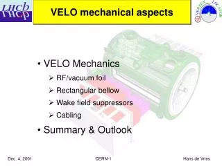
VELO mechanical design • Decouple access to silicon detectors • from access to primary vacuum • Baking up to 150 oC is possible • Use ultrapure neon venting • VELO and NEGs need not be rebaked • after access to Si detector Openings for feedthrough flanges (25’000 pins) Vertex detector half 120 cm 25 cm RF/Vacuum thin shield Exit window 1.5-2 mm thick Al Cooled Si sensors in secondary vacuum
Mixed-phase CO2 Cooling system Phase diagram CO2 • Advantages: • Radiation hard (used in nuclear power plants) • Non toxic (conc. < 5%), non flammable • Low pressure drop in microchannel tubes • Good thermodynamic properties • Widely available at low cost • No need to recover or recycle • Principle of operation: • CO2 is used in a two-phase cooling system. • The coolant is supplied as a liquid, the heat is taken away by evaporation. • LHCb VELO: in total, ~ 54 40 W of heat, each cooled by a pipe of OD=1.1/ID=0.9 mm. • Tested at NIKHEF: See LHCb 99-046/VELO • capacity of cooling pipe > 50 W • heat transfer coefficient between pipe and coolant > 2 W cm-2 K-1 critical point 100 solid liquid gas Pressure [bar] 10 vapor triple point 1 -80 -70 -60 -50 -40 -30 -20 -10 0 10 20 30 40 50 Temperature [°C]
Install wake field suppressors after mounting 2ary vacuum container Upstream is “easy”: mounted with large flange off Downstream is more delicate: mount through top flanges Wake field suppressors Aim: Provide a continuous conducting wall throughout the VELO to guide the mirror charge
Wake field suppressors • Current design: • Up/downstream suppressors • are identical • Material: CuBe (anneal, • form, harden at 400o C) • 16 segments (which deform • differently during movement) • Coat suppressors (?) • Press-fit to beam pipe • Mounting to detector box is • non-trivial Thickness: 100 m 194mm
LHCb VELO - LHC machine integration issues • The LHCb vertex detector system should not hamper LHC operation • Address: • vacuum issues • static and dynamic vacuum (ions, electrons and photons) • calculations and test measurements • radio-frequency issues • high frequency modes, losses, coupling impedance • calculations and test measurements • safety issues • define level of acceptability • perform risk analysis
Wake field simulations N. van Bakel VU Amsterdam • Aim: • acceptable heat dissipation in the VELO • minimize coupling impedance • Performed MAFIA simulations (frequency domain): • full tank model and smaller models • detector halves in position open and closed • compared various detector encapsulations with • different corrugation shape and depth • deal with complex non-symmetric structure! • time-consuming and CPU intensive • LHCb-99-041 “A first study of wake fields in the LHCb VD” • LHCb-99-043 “W. f. in the LHCb VD: strip shielding” • LHCb-99-044 “W. f. in the LHCb VD: alternative designs for the w. f. suppr.”
Si sensors ~35mm Al shield d Beam axis Wake field simulations (continued) 106 104 102 d=160mm 104 103 102 d=20mm Conclusion: no problematic resonant effects for corrugated encapsulation with corrugation depth d < 20 mm Under study: time domain(ABCI & MAFIA) low frequency slope of Im(Z//) loss factor k// Shunt resistance () 103 102 d=5mm 100 W limit 0 400 800 1200 Frequency (MHz)
RF tests at NIKHEF • Study: • Eigenmodes, impedance Z// • Effect of WF screens, open/close halves • RF fields inside secondary vacuum (pick-up) • Use: • Wire method • Multiple (rotatable) loop antennas • Reference LHC pipe 222 MHz 272 MHz 320 MHz First 3 measured eigenmodes of empty tank: 220, 270, 320 MHz Compare to simulation with MAFIA
Vacuum constraints for stable pressure in VELO: a first glance • LHC beam-gas life time limit 24 h requires LHC integrated density • tmax 1 1016 H2/cm2 . • H2 pressure of 10-7 mbar 2 m (300K) corresponds to0.005%of tmax. • rather “loose” constraint for stable pressure in VELO. • 10-7 mbar 1.2 m (H2 300K) 1.5 % of LHCb nominal luminosity • More serious: pumping life time of NEGs in LHCb beam pipe. • Estimate: pCO 10-8 mbar 6 m of pipe saturated in ~3 months (?)
Dynamic Vacuum • Dynamic vacuum phenomena must be taken into account • in the design of the LHCb vacuum system (including VELO): • Ion-, electron- and photon-induced desorption • Electron multipacting • stringent constraints on geometry and surface desorption properties, • e.g. for ion-induced desorption: local pumping speed and • surface materials must be chosen such that the critical current • Icrit > 2 2 0.85 A = 3.4 A Safety factor two beams
Dynamic pressure profile Unbaked VELO tank hi as for unbaked metal LHCb beam pipe (NEG saturated, i.e. not pumping) hi as for baked surface ion desorption yield (incident ion energy Eion ~ 300 eV) p (torr) Comments: • new VELO design is bakeable less outgassing and beam-induced desorption NEGs not saturated • most of COx desorption in this calculation is photon-induced if needed: reduce locally the photon flux A. Rossi, LHC-VAC No electron-induced desorption in the model
VELO vacuum system • Differential pumping system: • No valves between VELO 1ary vacuum and LHCbNEG-coated beam pipe • VELO 1ary vacuum base pressure (no beam) ~10-9 mbar • Detectors in 2ary vacuum ~10-4 mbar • Separation 1ary/2ary vacuum by thin Al foil • Developing gravity-controlled safety valve to protect the foil against • differential pressure • Coat foil with NEG or titanium if needed (see dyn. vac. phenomena) • Access to Si detectors decoupled from access to primary vacuum • In-situ baking of primary vacuum surfaces up to 150 oC • Use ultrapure neon venting so that VELO and NEGs need not be rebaked • after access to Si detector • Working on a detailed description of the VELO vacuum system: • components (pumps, ducts, ...) • monitoring and safety equipment • control system (PLC based) • describe static and transient modes
Thin vacuum foil Max p 500 mbar* Beryllium(1 mm thick): • very expensive… if at all feasible! • safety issues Aluminium (250 m thick): • “cheap & readily available” (compared to Beryllium) • NIKHEF: extensive prototyping program, welded 100 m on 300 m • Labour intensive: manufacture moulds, make foils, ~12 press/anneal cycles, etc. Max p 15 mbar* * Means irreversible deformation, no safety factor included. Values are approximate as mechanical properties can deviate substantially for the actual foil (hence, tests on prototypes are needed).
Gravity-controlled valve • weight ~ few grams, area ~ few cm2 • reacts to differential pressure ~ few mbar • no electrical power • no pressurized air • intrinsically safe solution to 1ary vacuum to auxiliary pump Use tandem valve to protect against both possible signs of differential pressure to 2ary vacuum
Risk Analysis • Purpose: To provide an objective basis for a constructive and methodical evaluation of the VELO design. • comprehensive overview of all risks involved • what riskscenarios, whatconsequences, whatprobabilitiesto occur ? • requirements/recommendations for a given design choice • what tests should be performed and what resultsobtained to make the chosen option acceptable ? • basis for a later, more detailed risk analysis • f.i. risk of “injuries to personnel” are not assessed in details, but believed to be downtime and equipment loss
Framework of Risk Analysis • Use same model as for CERN Safety Alarms Monitoring System (CSAMS) • (1) Identify undesired event (UE) • (2) Determine the consequence category of UE • (3) Use predefined table to fix maximum allowable frequency (MAF) • (4) Determine required frequency by reducing MAF by factor 100
Road map Feb 15 1st VELO presentation to LEMIC 2000 Jan 23 2nd VELO presentation to LEMIC • Fabricate prototype 250 m Al shield • Test mechanical properties of shield • Test vacuum safety devices (crash scenarios) • Measure Z//() • Build and test full scale CO2 cooling system • Manufacture vacuum tank • Full system test: • baking demonstration • pump-down procedure • venting with ultrapure neon • motion mechanics • etc. • (Milestones to be agreed upon in • 1st VELO review, Apr 3&4, 2001) Apr 3 1st VELO review with LHC 2001 May 28 Submit TDR to LHCC Presentation of TDR to LHCC Jul 4 Nov 5 Approval of TDR by RB Feb xx 2nd VELO review with LHC 2002 Feb yy 3rd VELO review with LHC (production readiness review) 2003
Road map (continued) Apr 1 2004 LHC octant test Sep 30 Last dipole delivered Mar 31 Installation of VELO at IP8 2005 Ring closed and cold Dec 31 Full machine commissioning Single beam First collisions (pilot run) Shutdown Jan 31 Mar 31 Apr 30 Jul 31 VELO commissioning, EMC tests, first tracks LHCb commissioning 2006 LHCb: run after... Physics run Feb 28 2007
Summary • After numerous LHC/LHCb meetings, including two LEMICs, the design of the VELO has matured to a system with • silicon detectors located in a 2ary vacuum system • thin separation foil (for RF and vacuum) protected by gravity-controlled and electrically controlled safety valves • a 2-phase CO2 cooling system in 2ary vacuum • decoupled access to Si detectors from access to 1ary vacuum system by using ultrapure inert gas venting • possibility to bake out up to T 150 oC • smooth conducting wall throughout setup for mirror charge (study wake field effects by simulations and tests with full scale model) • Major integration issues being addressed: dynamic vacuum, electron multipacting, impedance, RF losses, safety • Design has now clear support from LHC/VAC (see LEMIC jan/2001 and LHC-TC feb/2001) “door open” for TDR
Outlook • LHCb/VELO: continue extensive prototyping and testing • Mechanism for supervision by LHC was set up: • at least 3 reviews before installation at LHC • risk analysis to assess acceptability (not only LHC-VAC...) • perform all required tests before installation into LHC • Further interaction with LHC groups is essential: • vacuum: “sector” valves, more data and simulations needed on dyn. vac. effects, e.g. hi of saturated NEGs, photon flux at IP8, e-multipacting, etc. • choice and configuration of equipment: vacuum pumps, valves, diagnostics equipment, controls (PLCs), etc.(radiation environment) • beam failure scenarios and IP8, radiation monitors, etc. • Aim: full system setup with Si detector modules in LHC during single beam operation in feb+mar 2006