Download
1 / 62
620 likes | 625 Views
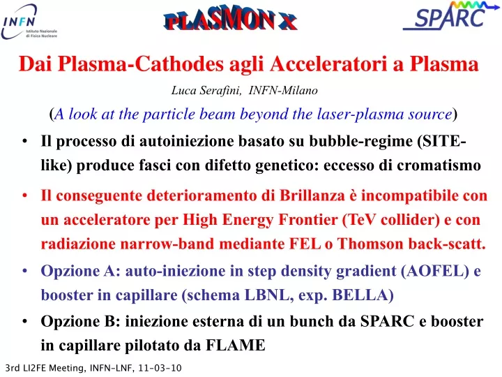
Dai Plasma-Cathodes agli Acceleratori a Plasma. Luca Serafini, INFN-Milano. ( A look at the particle beam beyond the laser-plasma source ). Il processo di autoiniezione basato su bubble-regime (SITE-like) produce fasci con difetto genetico: eccesso di cromatismo.

E N D
Dai Plasma-Cathodes agli Acceleratori a Plasma Luca Serafini, INFN-Milano (A look at the particle beam beyond the laser-plasma source) • Il processo di autoiniezione basato su bubble-regime (SITE-like) produce fasci con difetto genetico: eccesso di cromatismo • Il conseguente deterioramento di Brillanza è incompatibile con un acceleratore per High Energy Frontier (TeV collider) e con radiazione narrow-band mediante FEL o Thomson back-scatt. • Opzione A: auto-iniezione in step density gradient (AOFEL) e booster in capillare (schema LBNL, exp. BELLA) • Opzione B: iniezione esterna di un bunch da SPARC e booster in capillare pilotato da FLAME
1018 1017 AOFEL I [kA] 1016 1015 1014 1013 n[m] Self-Inj chromaticity SPARX X-ray FEL @ 1 pC SPARC Photo-injectors The Brightness Chart [A/(m.rad)2]
M. Migliorati Asymptotic linear growth of norm. emittance with distance, as predicted by formula Which gives, for C. Benedetti’s simulations of SITE, 500 mm.mrad per meter of free space drift (matches upper plot in first 10 cm drift before quadrupoles)
x envelope and emittance free diffraction in vacuum RETAR (A. Rossi) no description of plasma vacuum interface Gruppo di Studio LI2FE Particle & Radiation Beam Dynamics M. Ferrario coord.
AOFEL CO2 envelope CO2 focus r m] TiSa envelope TiSa pulse e- beam plasma Lsat=10LG=1.3 mm (=0.002) Z [m] Lchrom=s02/(eDg/g)=2.5 cm
11thICATPP , Villa Olmo, Como, Italy, Oct. 5th, 2009 Laser 1000 TW 40 fs < 1 m ~10 GeV e- beam Multi-GeV beams BELLA @ LBNL 10 GeV PWFA • Two-stage design • Need 40 J in 40 fs laser pulse • BELLA Project: 1 PW, 1 Hz laser • Will be followed by staging at multi-GeV energies • 10 GeV beam allow positron production, XFEL!
LIFE: the Plasma Accelerator(exploitation of velocity bunching and synchronization) • Injected Bunch: 13pC, 150MeV, 0.6 mm.mrad, sx 3.0 mm rms, sz 2.4 mm rms [1KA peak current] • Laser: 7J in 35fs, w0=32.5 mm, w0_inj=135 mm, guided over 30 ZR. • Plasma: Density profile increasing from 0.6e17 cm-3 up to 0.8e17 cm-3 , “tapered channel” for pulse guiding. Acceleration length about 15cm. • Numerics: Window mobile at v=c, grid sampling at 46points/ lp e 26 points/w. Bunch described by 40000 macro-particles
Dynamics in longitudinally inhomogenous plasmas • Il controllo della velocita’ di fase dell’onda si ottiene profilando adeguatamente la densita’ del plasma
External Injection of a 10 fs 15 pC electron bunch generated bySPARC photoinjector into a LWFA <E> = 2.01 GeV DE/E = 0.8% rms en=0.6 mm
1018 1017 AOFEL I [kA] 1016 1015 1014 1013 n[m] Self-Inj SPARX Ext-Inj X-ray FEL @ 1 pC SPARC Photo-injectors The Brightness Chart [A/(m.rad)2]
Targetring • Hollow fiber • Gas jet with density step • Gas cell with density modulation • Etc..
11thICATPP , Villa Olmo, Como, Italy, Oct. 5th, 2009 Reinventing the Accelerator for the High Energy Frontier Advanced Accelerators for Particle Physics and Applications(X-ray FELs, Compact Light Sources, particle beams for medicine, etc. and their positive feedbacks on HEP accelerators!) James B. Rosenzweig1, Luca Serafini2 1UCLA Dept. of Physics and Astronomy 2INFN - Milan Talk available at http://pcfasci.fisica.unimi.it/Homepage.html
Medicine Light sources (3rd Generation) Nuclear physics X-ray FEL Historical schematic of accelerators:Particle physics leads, spin-offs follow quickly Betatron FFAG, etc. Superconducting Circular Collider Circular Collider Synchrotron VLHC? Cyclotron Muon Collider? 2030 1930 Ion Linear Accelerators Ultra-High Energy LC? Electrostatic Accelerators Electron Linear Accelerators Electron Linear Colliders Laser/Plasma Accelerators? 11thICATPP , Villa Olmo, Como, Italy, Oct. 5th, 2009
Ultra-short beam application:IR wavelength PWFA • Ultra-high brightness, fs beams impact HEP also! • Use 20 pC LCLS beam in high n plasma • In “blowout” regime: total rarefaction of plasma e-s • Beam denser than plasma • Very nonlinear plasma dynamics • Pure ion column focusing for e-s • Linac-style EM acceleration • General measure of nonlinearity: R (mm) Z (mm) MAGIC simulation of blowout PWFA case
With 2 fs LCLS beam we should choose • For 2 pC beam, we have • 1 TV/m fields (!) • Also w/o plasma (ionization) • New frontier in atomic physics • Collaboration formed • UCLA-SLAC-USC • Technical issues address OOPIC simulation of LCLS case 1 TV/m accelerating field: a dream for a table-top TeV-class e-e+ collider?
Sub-fs e- 1 pC bunches @ SPARC First attempt (A. Bacci with gen. algorithm)
Conclusioni • Citando Chen Joshi di UCLA, che ha dichiarato all’ ICFA workshop on Laser and Plasma Accelerators (LPAW09, Kardamyli, june 2009) : • “We need to move LPA experiments from the Shoot-and-See towards a real Accelerator” • Abbiamo una window of opportunity di circa 2-3 anni per mettere in funzione a LNF un vero Acceleratore a Plasma che sia un precursore di un TeV-class collider
Unprecedented results in Application Experiments due to unique beams available LIFE Window of Opportunity (5 year catch) Crucial Role in advancing new technologiesfor the High Energy Frontier needless to say… we need the correct Spirit of sharing Expertise and Instrumentation More Details in: http://www.lnf.infn.it/acceleratori/sparc/LIFE/LIFE.html http://pcfasci.fisica.unimi.it/Homepage.html
Ultra-short XFEL pulses:motivation and feedback to HEP • Investigations at atomic electron spatio-temporal scales • Angstroms-nanometers (~Bohr radius) • Femtoseconds (electronic motion, Bohr period) • Femtochemistry, etc. • 100 fs accessible using standard techniques • Many methods proposed for the fsec frontier • Use “clean” ultra-short electron beam • Myriad of advantages in FEL and beam physics • Robust in application: XFEL, coherent optical source, PWFA… How a HEP Spin-Off, the X-ray FEL, can return a positive feedback in advancing Accelerators toward the High Energy Frontier
Ultra-short pulses at SPARX Q=1 pC case • Scaling indicates use of ~1 pC beam for single spike • For 1 pC, sz only 4.7 mm after velocity bunching • Use June 2008 version of SPARX lattice • compression no longer at end, at 1.2 GeV (Final 2.1 GeV) • Very high final currents, • some CSR emittance growth, for 1 pC • Longitudinal tails, higher peak brightness (2 orders of magnitude!)
FEL performance: 1 pC, 2 fs e- bunch z • Single spike with some structure • > 1 GW peak power at saturation (30 m) • 480 attosecond rms pulse at 2 nm at SPARX s (mm) z (m) l (nm)
sp=2 px Den/en=1 en=1 x s0=0.5 after drift d=2 px sp=0.71 Den/en=0.18 en=1 x s0=1.41
Emittance Dilution due to Chromatic Effects on a beam emerging from a focus of spot size s0, drifting to a distance d Valid also for protons/ions SPARC en=1 mm.mrad, s0= 200 m, g=300, Dg/g=0.6%, d=10 m Den =0.005 mm.mrad Self-Inj en=2 mm.mrad, s0= 1 m, g=2000, Dg/g=2%, d=1 m Den =40 mm.mrad
Brightness good enough to drive a X-ray FEL B_peak=2I/e2=3.5.1016A/m2
AOFEL • injection by longitudinal nonlinear breaking of the wave • at a density downramp looks one of the most promising • since it can produce e-beams having both low energy • spread and low transverse emittance. • electromagnetic undulator made by a laser pulse • counter propagating respect to the electron beam
First stage:LWFA with a gas jet modulated in areas of different densities with sharp density gradients.
Transverse and longitudinal phase and configuration spaces @ 1 cm
Transverse and longitudinal phase and configuration spaces @ 92 cm
Space charge energy spread No Space charge energy spread
No Space charge No energy spread SPARC beam Space charge energy spread
SPARC(Sorgente Pulsata e Amplificata di Radiazione Coerente) and PLASMONX(PLasma Acceleration @ Sparc & MONochromatic X-rays) Unique worldwide at these level of combined beam performance High Brightness Electron Beams (ps to fs bunch length) Synchronized to fs level High Intensity Laser Beams (20-100 fs pulses)
W0=23 m, T=17 fs I=8.5*1018 W/cm2 , E=2.4 J Aladyn, see C. Benedetti’s talk
Best slices Slice analysis: length of each slice
Longitudinal phase space and density profile Selection of best part in the bunch: 40 pC in 2 fs (600 nm) projected rms n = 0.7 m <> <>