Download
1 / 29
290 likes | 432 Views
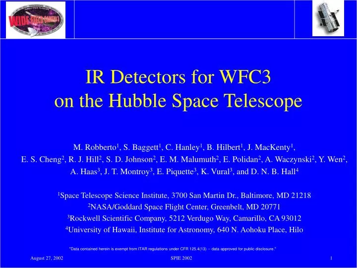
IR Detectors for WFC3 on the Hubble Space Telescope. M. Robberto 1 , S. Baggett 1 , C. Hanley 1 , B. Hilbert 1 , J. MacKenty 1 , E. S. Cheng 2 , R. J. Hill 2 , S. D. Johnson 2 , E. M. Malumuth 2 , E. Polidan 2 , A. Waczynski 2 , Y. Wen 2 ,

E N D
IR Detectors for WFC3 on the Hubble Space Telescope M. Robberto1, S. Baggett1, C. Hanley1, B. Hilbert1, J. MacKenty1, E. S. Cheng2, R. J. Hill2, S. D. Johnson2, E. M. Malumuth2, E. Polidan2, A. Waczynski2, Y. Wen2, A. Haas3, J. T. Montroy3, E. Piquette3, K. Vural3, and D. N. B. Hall4 1Space Telescope Science Institute, 3700 San Martin Dr., Baltimore, MD 21218 2NASA/Goddard Space Flight Center, Greenbelt, MD 20771 3Rockwell Scientific Company, 5212 Verdugo Way, Camarillo, CA 93012 4University of Hawaii, Institute for Astronomy, 640 N. Aohoku Place, Hilo
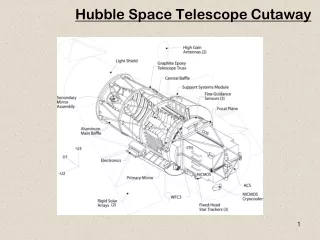
WFC3 layout IR M1 Mirror IR Detector UVIS Corrector Mech. Cold Enclosure RCP/ Cold Stop UVIS Detector IR Filter Wheel Mechanism IR Corrector Mech. CSM IR Fold Mirror Shutter Mechanism Baffles SOFA Mechanism Calibration Subsystem Optical Bench (In Phantom) UVIS Optical Path (Blue) IR Optical Path (Red) UVIS M2 Mirror POM
WFC3 IR channel The zodiacal scattering and the HST temperature create a minimum of background at ~ 1.6 mm. A detector with cut-off at ~ 1.7 mm can be operated at ~150K. No need for liquid nitrogen. Extended lifetime. WFC3-1R FPA
WFC3-1R FPA • Producer: Rockwell Scientific Company • Type: HgCdTe with 1.72mm cutoff - MBE grown on ZnCdTe substrate - Hawaii-1R MUX • Operating T: 150K • Pixel size: 18 mm • Format: 1024 1024 pixels - 1014 1014 active pixels - 5 outer rows/column with reference pixels
Hawaii-1R MUX design Quadrant 2 512x512 (507x507 photoactive) Quadrant 4 512x512 (507x507 photoactive) Hawaii-1R MUX ses reference pixels Quadrant 1 512x512 (507x507 photoactive) Quadrant 3 512x512 (507x507 photoactive) 1014 1014 active pixels 1014 5 reference pixels
Hawaii-1R Unit Cell Vrst Vrst Vrst Vcelldrain Vcelldrain Vcelldrain Frst Frst Frst pn Cref bus bus Cref bus Vsub Fread Vsub Fread Fread Vsub Inboard reference pixels Offboard reference pixels Active pixels
WFC3-1R specs Quantum Efficiency • Range and absolute value see viewgraph • Stability 0.5 %/hr p-p; 1.0 %/month
WFC3-1R specs • Amplifier glow <10 e/pix/read at the center • <400 e/pix/read at the border (<5%) • Linearity >95%, correctable to >99.7% • Full well capacity 100,000 e/pix (150,000 goal) • Pixel-to pixel response • uniformity better than 2%; 1% @ 1000-1800nm (0.5% goal) • stability <0.2 % over 1 hr ; <1% over 2 months • Radiation hardness • Absolute sensitivity <1,000 e/event • Stability (SAA) <0.1/e/s/pix after 5min > 90%
Program status • Original Rockwell Scientific WFC3 flight detector contract started almost 2 years ago • 4 Lots of FPAs completed by the end of November 2001 • 2 Lots of detectors completed by the end of June 2002 • 52 FPA have been hybridized • 24 FPAs have been delivered to NASA/GSFC for test • Flight candidates selected • Lot 7 started July 2002 • First FPAs in early test phase at RSC • Complete delivery by November 2002
Cutoff Spatial Uniformity FPA #15 1720 nm 1400 nm
QE summary • Early detectors (before lot 6) exhibit • long wavelength QE better than specification • low QE at short wavelengths • With Lot 6/process B detectors low wavelength QE has been restored • Lot 6/process A detectors show excellent QE at all wavelengths.
Dark Current FPA 43 60min dark
FPA#32 1m 30m 1m 60m 1m 90m 1m 120m 1m 150m 1m 180m 1m 1m 30m 1m 60m 1m 90m 1m 120m 1m 150m 1m 180m 1m
FPA#32 1m 30m 1m 60m 1m 90m 1m 120m 1m 150m 1m 180m 1m 1m 30m 1m 60m 1m 90m 1m 120m 1m 150m 1m 180m 1m
FPA 32/50 Stability Comparison “Settled” dark current level. Data taken immediately after 3/4 full-well flat field. “Reset anomaly” peaks follow a trend line. Time (hours)
Dark Current Summary • Dark current specification is less than 0.2 e-/pixel/sec. • Dark current levels as low as 0.02 e-/pixel/sec have been achieved • In Lot 3 and Lot 6 devices the dark current is not be stable after power cycling, bias change, or exposure to light. • Settling times range from a few minutes for some devices, to 10’s of hours for most of the high-QE devices. • Precludes simple on-orbit calibration (remembers the last exposure). • Powering down the detector on-orbit will be an efficiency impact (long delays before data taking can resume). • Lot 4 devices show both low and stable dark current
Readout Noise Active pixels Reference pixels
RON table Double Correlated Sampling Gain = 5.9mV/adu measured on FPA#43 and #50
Readout Noise summary • Best noise performance is ~30e-/DCS • Noise higher in the detector pixels than in the reference pixels. • Source in the detector material rather than in the mux • Evidence of some 1/f low-frequency drift (below ~10 KHz) • typical of surface state trapping • White-spectrum excess noise reduces with temperature roughly as the square-root of temperature • suggests Johnson noise from a resistive element
Key Lots are 4 and 6 • Lot 3 and 4 • Part of the original flight detector contract. • Cutoff demonstrated • Good dark current • Good stability (only lot 4) • Acceptable noise (only lot 4) • Poor QE • Lot 5 and 6 • First iteration. • Exceptionally good QE (lot 6) • Poor stability • Higher readout noise.
Lot 7 goals In priority order: • Maintain QE enhancement process steps used for the Lot 6 devices. • Improve or remove the dark current instability (like what was achieved in the Lot 4 devices). • Reduce the readout noise.
Lot 7 Processing Status and Schedule • Split processing of two, 4-wafer batches for processing risk mitigation • 4 devices per wafer • All 8 wafers have been grown • First 4 wafers have been processed • Polishing done • A/R Coating done • Dicing done • Performance Evaluation Chip (PEC) under test • First FPAs are being hybridized and tested at RSC • The second batch processing will follow.