Download
1 / 55
570 likes | 596 Views
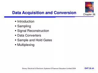
Lesson 9 Data Acquisition and Waveforms. TOPICS Plug-in DAQ devices Data Acquisition in LabVIEW Analog Input Data Logging Analog Output Counters Digital I/O. Overview and Configuration. Fundamental task of a DAQ system is to measure or generate real-world physical signals

E N D
Lesson 9Data Acquisition and Waveforms TOPICS Plug-in DAQ devices Data Acquisition in LabVIEW Analog Input Data Logging Analog Output Counters Digital I/O
Overview and Configuration • Fundamental task of a DAQ system is to measure or generate real-world physical signals • DAQ system consists of: • Transducers • Signal Conditioning • Plug-in DAQ device • Driver • Software
Measurement Software Framework • NI-DAQ contains: • Traditional NI-DAQ • NI-DAQmx
DAQ Hardware Configuration Measurement & Automation Explorer (MAX)
Channels and Tasks Channel names Sine Wave 1 ai 0 Signals Sine Wave 2 ai 1 ai 2 Sine Wave 3 Tasks Timing and Triggering
NI-DAQmx versus Traditional NI-DAQ Productivity Performance Accuracy Quality Compatibility • Best • Good Fair
Data Acquisition in LabVIEW • NI-DAQmx • Next generation driver: • VIs for performing a task • One set of VIs for all measurement types • Traditional NI-DAQ • Specific VIs for performing: • Analog Input • Analog Output • Digital I/O • Counter operations
NI-DAQmx Data Acquisition Single set of VIs used to perform analog I/O, digital I/O, and counter operations • DAQ Assistant Express VI • Quickly and easily program the DAQ device • Creates a local task • Most applications can use the DAQ Assistant Express VI
NI-DAQmx Data Acquisition Task Types • Measurement type can be: • Analog Input • Analog Output • Counter Input • Counter Output • Digital I/O
Analog Input Analog Input task is specific to the measurement
Analog Input Task Timing and Triggering Configures the number of samples and sample rate for the task Configures the start and reference triggers for the task
Data Logging • It is often necessary to permanently store data that is acquired from the DAQ device • LabVIEW includes the ability to read and write a LabVIEW Measurement File • LabVIEW Measurement File is an ASCII text file
Analog Output Analog Output task is specific to the generation type
Analog Output Task Timing and Triggering Configures the number of samples and sample rate for the task Configures the start and reference triggers for the task
Counters • A counter is a digital timing device • Typical uses of a counter: • Event counting • Frequency measurement • Period measurement • Position measurement • Pulse generation Gate Output Count Register Source Count register – Stores the current count of the counter Source – Input that causes the counter to increment each time it toggles Gate – Input that is used to enable or disable the function of the counter Output – Signal that generates pulses or a series of pulses
Digital Input and Output • Digital I/O can read from or write to a line or an entire digital port • A digital port is a collection of digital lines
Summary • MAX is the primary configuration and testing utility that is available for the DAQ device. • The DAQ Assistant is used to configure the DAQ device and perform data acquisition. • Most application can use the DAQ Assistant. For applications that require advanced timing and synchronization use the VIs that come with NI-DAQmx. • The DAQ Assistant can perform Analog Input, Analog Output, Digital I/O, and Counter operations.
Lesson 10Instrument Control TOPICS Instrument Control Overview GPIB Communication and Configuration Instrument I/O Assistant Virtual Instrument Software Architecture (VISA) Instrument Drivers Serial Port Communication Waveform Transfers
Instrument Control Overview • Control any instrument if you know the following: • Type of connector on the instrument − Type of cables needed • Electrical properties involved − Communication protocols used • Software drivers available Instruments Computer
GPIB Communication GPIB Interface GPIB Instruments GPIB Cable
Standards Introduction HP designs HP-IB (Hewlett Packard Interface Bus) 1965 HP-IB becomes IEEE 488 1975 1987 IEEE 488.2 adopted IEEE 488 becomes IEEE 488.1 1990 SCPI (Standard Commands for Programmable Instruments) added to IEEE 488.2 1992 IEEE 488.2 revised HS488 proposed 1993 HS488 approved 1999
DIO1 DIO5 1 13 DIO2 DIO6 DIO3 DIO7 DIO4 DIO8 EOI REN DAV GND (TW PAIR W/DAV) NRFD GND (TW PAIR W/NRFD) NDAC GND (TW PAIR W/NDAC) IFC GND (TW PAIR W/IFC) SRQ GND (TW PAIR W/SRQ) ATN 12 24 GND (TW PAIR W/ATN) SHIELD SIGNAL GROUND GPIB Hardware Specifications • Max cable length between devices = 4 m (2 m average) • Max cable length = 20 m • Max number of devices = 15 (2/3 powered on)
GPIB Software Architecture — Windows Diagnostics Tools: GPIB Diagnostic Tool NI-Spy Instrument Driver VIs Driver Software (*.DLL) NI-VISA Interface Board (GPIB, PXI, VXI, computer based, etc.) LabVIEW Configuration Tools: Measurement & Automation Explorer
Configuring GPIB Board and Instruments Measurement & Automation Explorer (MAX)
What is the Instrument I/O Assistant? • Accessed through a LabVIEW Express VI • Sets up device communication and data parsing step by step through a configuration interface
Platform independent VISA is the backbone of the IVI and Plug & Play Instrument Drivers Virtual Instrument Software Architecture VISA Serial GPIB VXI PXI • Interface independent • Must know SCPI command set to program directly with VISA
VISA Terminology • Resource—Instrument, Serial Port, or Parallel Port • Session—Connection to a Resource • Instrument Descriptor—Resource location • Format: Interface Type::Address::INSTR • Examples:
Instrument Descriptor Syntax • Resource Name contains interface info • VISA Aliases also work Interface Resource Name Grammar Serial ASRL[board][::INSTR] GPIB GPIB[board]::primary address[::INSTR] VXI VXI[board]::VXI logical address[::INSTR] GPIB-VXI GPIB-VXI[board][::GPIB-VXI primary address]::VXI logical address[::INSTR]
VISA Resource Name • Exact name and location of the instrument • Use the VISA Resource Name control • You can specify the full resource name of the VISA Alias
Instrument Drivers • More than 1200 LabVIEW Instrument drivers • Programming simplified to high-level API
Installing and Finding Instrument Drivers • Drivers available at ni.com/idnet • Install the instrument driver VI Library into LabVIEW 7.0\instr.lib directory • Access drivers from Functions»Input»Instrument Drivers subpalette
IDNET - Instrument Driver Network • Learn about drivers • Get help with developing drivers • Submit your driver to the network • Download drivers
Instrument Driver VIs • Initialize • • • • Configure • • • • • • • • • Action/Status • • • • • • • • • • • • • Data • • • • • • • • • • • • • • • • • • • • • • • • • • • Utility • • • • • • • • • • • • • • • • • • • • • • • • • • • • • • • • Close • • • • • • • • • • • • • • • • • • • • • • • • • • • • • • • • • • • • • •
Instrument Driver Inputs and Outputs HP34401A Initialize.vi • Instrument Descriptor • VISA Sessions • A connection or link to a specific instrument • Created after instrument is initialized • Used throughout VI whenever you communicate with that specific instrument • Error cluster
Putting It All Together • Initialize instrument • Do operation(s) • Close instrument • Check error status
Serial Communication • Popular means of communication between computer and peripheral device • Data sent one bit at a time across the cable • Used for low transfer rates or long distances • Only a cable is needed since most computers have at least one available serial port PC Serial Port RS-232 Cable RS-232 Instrument
Serial Hardware Connection • RS-232 • DCE or DTE configurations • 9-pin or 25-pin • RS-422 • DCE or DTE • 8-pin • RS-485 • Multidrop Pin DTE DCE 1 DCD Input Output 2 RxD I O 3 TxD O I 4 DTR O I 5 Com - - 6 DSR I O 7 RTS O I 8 CTS I O 9 RI I O
Serial Communication Terminology • Baud rate – bits per second • Data bits – inverted logic and LSB first • Parity – optional error-checking bit • Stop bits – 1, 1.5, or 2 inverted bits at data end • Flow control – hardware and software handshaking options
Using the Instrument I/O Assistant with Serial • Select COMX as the instrument address • Use the I/O Assistant as done with GPIB
Summary • LabVIEW can communicate with any instrument that connects to your computer if you know the interface type • Use the Measurement & Automation Explorer (MAX) to detect, configure, and test your GPIB interface and instruments • Use the Instrument I/O Assistant for easy and fast GPIB and serial programming. • An instrument driver eliminates the need for your to have detailed knowledge of the specific strings used by an instrument • Instrument Library – more than 2000 instruments supported • Instrument driver VIs share a common hierarchy and come with an example to help you get started
Lesson 11VI Customization TOPICS Configuring Appearance of Front Panel SubVI Front Panels Keyboard Shortcuts VI Properties Customizing Palettes
Customizing VI Properties • Access VI Properties by right-clicking the icon pane or selecting it from the File menu • Affects every instance of that VI in all applications
Window Appearance Only affects VI panel while VI is running
Window Size • Set minimum and current panel size • Adjust size of panel relative to the monitor • Scale objects on panel as window resizes
Creating Pop-Up Panels – Every Instance • Use Top-Level Application Window or Dialog appearance types • Create custom window appearance
Creating Pop-Up Panels – Single Instance Access SubVI Node Setup by right-clicking on subVI icon on calling VI’s diagram
Key Navigation Assigns keyboard strokes to front panel controls