Download
1 / 61
610 likes | 712 Views
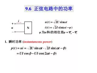
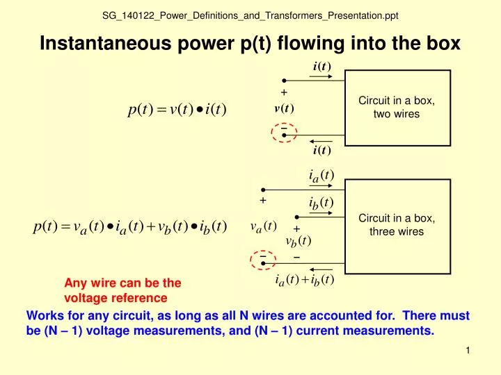
+ −. Circuit in a box, two wires. + −. Circuit in a box, three wires. + −. Instantaneous power p(t) flowing into the box. Any wire can be the voltage reference.

E N D
+ − Circuit in a box, two wires + − Circuit in a box, three wires + − Instantaneous power p(t) flowing into the box Any wire can be the voltage reference Works for any circuit, as long as all N wires are accounted for. There must be (N – 1) voltage measurements, and (N – 1) current measurements.
Two-wire sinusoidal case zero average Power factor Average power
compare Root-mean squared value of a periodic waveform with period T Compare to the average power expression The average value of the squared voltage Apply v(t) to a resistor rms is based on a power concept, describing the equivalent voltage that will produce a given average power to a resistor
Root-mean squared value of a periodic waveform with period T For the sinusoidal case
Given single-phase v(t) and i(t) waveforms for a load • Determine their magnitudes and phase angles • Determine the average power • Determine the impedance of the load • Using a series RL or RC equivalent, determine the R and L or C
Determine voltage and current magnitudes and phase angles Using a cosine reference, Voltage cosine has peak = 100V, phase angle = -90º Current cosine has peak = 50A, phase angle = -135º Phasors
Thanks to Charles Steinmetz, Steady-State AC Problems are Greatly Simplified with Phasor Analysis (no differential equations are needed) Time Domain Frequency Domain Resistor voltage leads current Inductor current leads voltage Capacitor
Complex power S Projection of S on the imaginary axis Q P Projection of S on the real axis is the power factor Active and Reactive Power Form a Power Triangle
Consider a node, with voltage (to any reference), and three currents IA IB IC Question: Why is there conservation of P and Q in a circuit? Answer: Because of KCL, power cannot simply vanish but must be accounted for
Voltage and Currentin phase Q = 0 Voltage leads Current by 90° Q > 0 Current leads Voltage by 90° Q < 0 Voltage and Current Phasors for R’s, L’s, C’s Resistor Inductor Capacitor
Complex power S Projection of S on the imaginary axis Q P Projection of S on the real axis
Resistor also so Use rms V, I ,
Inductor also so Use rms V, I ,
Capacitor also so , Use rms V, I
Active and Reactive Power for R’s, L’s, C’s (a positive value is consumed, a negative value is produced) Active Power P Reactive Power Q Resistor Inductor Capacitor source of reactive power
Now, demonstrate Excel spreadsheet EE411_Voltage_Current_Power.xls to show the relationship between v(t), i(t), p(t), P, and Q
0.05 + j0.15 pu ohms PL + jQL PR + jQR /0 ° VR = 1.010 / - 1 0 ° VL = 1.020 IS IcapL IcapR j0.20 pu mhos j0.20 pu mhos A Transmission Line Example Calculate the P and Q flows (in per unit) for the loadflow situation shown below, and also check conservation of P and Q.
0.05 + j0.15 pu ohms PL + jQL PR + jQR /0 ° VR = 1.010 / - 1 0 ° VL = 1.020 IS IcapL IcapR j0.20 pu mhos j0.20 pu mhos
V 0 0 < D < 1 DT T RMS of some common periodic waveforms Duty cycle controller By inspection, this is the average value of the squared waveform
RMS of common periodic waveforms, cont. Sawtooth V 0 T
V 0 V 0 V 0 V 0 V 0 V 0 0 -V RMS of common periodic waveforms, cont. Using the power concept, it is easy to reason that the following waveforms would all produce the same average power to a resistor, and thus their rms values are identical and equal to the previous example
a b c n Three-phase, four wire system Reference Three Important Properties of Three-Phase Balanced Systems • Because they form a balanced set, the a-b-c currents sum to zero. Thus, there is no return current through the neutral or ground, which reduces wiring losses. • A N-wire system needs (N – 1) meters. A three-phase, four-wire system needs three meters. A three-phase, three-wire system needs only two meters. • The instantaneous power is constant
Observe Constant Three-Phase P and Q in Excel spreadsheet 1_Single_Phase_Three_Phase_Instantaneous_Power.xls
Imaginary V V = V – V cn ab an bn V = V – V ca cn an 30° Real V an 120° V bn V = bc V – V b n c n The p hasors are rotating counter - clockwise . 3 The magnitude of line - to - line voltage phasors is times the magnitude of line - to - neutral voltage phas ors.
Imaginary V V = V – V cn ab an bn V = V – V ca cn an I c I ca 30° I ab Real V I an a Line currents I , I , and I a b c I I bc b Delta currents I , I , and I ab bc ca I c c V bn I ca Balanced Sets Add to Zero in Both I bc Time and Phasor Domains I + I + I = 0 a b c I a b I b b a V + V + V = 0 an b n cn V = bc V – V – Vab + bn cn V + V + V = 0 ab bc ca I a 1 Conservation of power requires that the magnitudes of delta currents I , I , and I are ab ca bc 3 times the magnitude of line currents I , I , I . a b c
c c I c I c – V a n n + a a b b I – V + b ab I b – V + ab I a I a The Two Above Sources are Equivalent in Balanced Syst ems (i.e., same line currents I , I , I and phase - to - phase voltages V , V , V in both cases ) a b c ab bc ca
c KCL: I = I + I + I n a b c I c But for a balanced set, I + I + I = 0, so I = 0 Z a b c n I n n Z Z a b – V + ab I b I a Ground (i.e., V = 0) The Experiment: Opening and closing the switch has no effect because I is already zero for a three - phase n balanced set. Since no current flows, even if there is a resistance in the grounding path, we must conclude that V = 0 at the neutral point (or equivalent neutral point) of any balanced three phase load or source in a bala nced n system. This allows us to draw a “one - line” diagram (typically for phase a) and solve a single - phase problem. Solutions for phases b and c follow from the phase shifts that must exist.
3 Z l ine c c I c 3Z 3Z load load a a b b Z l ine I 3Z a load – V + ab Z l ine I b Balanced three - phase systems, no matter if they are delta connected, wye connected, or a mix, are easy to solve if you follow these steps : Z l ine 1. Convert the entire circuit to an equivalent wye with a a a I a ground ed neutral . 2. Draw the one - line diagram for phase a , recognizing that phase a has one third of the P and Q . 3. Solve th e one - line diagram for line - to - neutral voltages and + line currents . The “One - Line” Z load Van 4. If needed, compute l ine - to - neutral voltages and line currents Diagram – for phases b and c using the ±120° relationships. 5. If needed, compute l ine - to - line voltages and delta currents n using the and ± 30 ° relationships. n
Now Work a Three-Phase Motor Power Factor Correction Example A three-phase, 460V motor draws 5kW with a power factor of 0.80 lagging. Assuming that phasor voltage Van has phase angle zero, • Find phasor currents Ia and Iab and (note – Iab is inside the motor delta windings) • Find the three phase motor Q and S • How much capacitive kVAr (three-phase) should be connected in parallel with the motor to improve the net power factor to 0.95? • Assuming no change in motor voltage magnitude, what will be the new phasor current Ia after the kVArs are added?
Part c. Draw a phasor diagram that shows line currents Ia, Ib, and Ic, and load currents Iab, Ibc, and Ica. Now Work a Delta-Wye Conversion Example
Φ jXs Rs Ideal Transformer jXm Rm 7200:240V Turns ratio 7200:240 (30 : 1) (but approx. same amount of copper in each winding) 7200V 240V Single-Phase Transformer
Isc + Vsc - Short circuit test: Short circuit the 240V-side, and raise the 7200V-side voltage to a few percent of 7200, until rated current flows. There is almost no core flux so the magnetizing terms are negligible. Φ Turns ratio 7200:240 (but approx. same amount of copper in each winding) Short Circuit Test jXs Rs Ideal Transformer jXm Rm 7200:240V 7200V 240V
+ Voc - Φ Turns ratio 7200:240 (but approx. same amount of copper in each winding) Open Circuit Test Ioc jXs Rs Ideal Transformer jXm Rm 7200:240V 7200V 240V Open circuit test: Open circuit the 7200V-side, and apply 240V to the 240V-side. The winding currents are small, so the series terms are negligible.
jXs Rs Ideal Transformer jXm Rm 7200:240V 7200V 240V 1. Given the standard percentage values below for a 125kVA transformer, determine the R’s and X’s in the diagram, in Ω. 2. If the R’s and X’s are moved to the 240V side, compute the new Ω values. Single Phase Transformer. Percent values are given on transformer base. Winding 1 kv = 7.2, kVA = 125 Winding 2 kv = 0.24, kVA = 125 %imag = 0.5 %loadloss = 0.9 %noloadloss = 0.2 %Xs = 2.2 Load loss Xs No load loss Magnetizing current 3. If standard open circuit and short circuit tests are performed on this transformer, what will be the P’s and Q’s (Watts and VArs) measured in those tests?
jXs Rs Ideal Transformer jXm Rm X / R Ratios for Three-Phase Transformers • 345kV to 138kV, X/R = 10 • Substation transformers (e.g., 138kV to 25kV or 12.5kV, X/R = 2, X = 12% • 25kV or 12.5kV to 480V, X/R = 1, X = 5% • 480V class, X/R = 0.1, X = 1.5% to 4.5%
Saturation – relative permeability decreases rapidly after 1.7 Tesla Relative permeability drops from about 2000 to about 1 (becomes air core) Magnetizing inductance of the core decreases, yielding a highly peaked magnetizing current Linear Scale Log10 Scale