Download
1 / 15
290 likes | 1.06k Views
Demodulation of DSB-SC AM Signals. Suppose that the DSB-SC AM signal u(t) is transmitted through an ideal channel (with no channel distortion and no noise) Then the received signal is equal to the modulated signal, Suppose we demodulate the received signal by

E N D
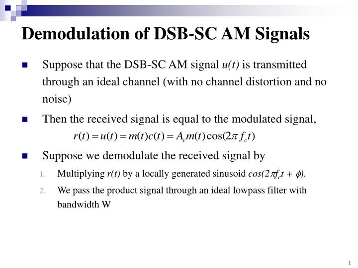
Demodulation of DSB-SC AM Signals • Suppose that the DSB-SC AM signal u(t) is transmitted through an ideal channel (with no channel distortion and no noise) • Then the received signal is equal to the modulated signal, • Suppose we demodulate the received signal by • Multiplying r(t) by a locally generated sinusoid cos(2fct + ). • We pass the product signal through an ideal lowpass filter with bandwidth W
Demodulation of DSB-SC AM Signals • The multiplication of r(t) with cos(2fct + ) yields • Since the frequency content of m(t) is limited to W Hz, where W << fc, the lowpass filter can be designed to eliminate the signal components centered at 2 fcand to pass the signal components centered at f = 0 Frequency-domain representation of the DSB-SC AM demodulation.
Demodulation of DSB-SC AM Signals • Consequently, the output of the ideal lowpass filter • Note that m(t) is multiplied by cos() • So the power in the demodulated signal is decreased by a factor of cos2 • Thus, the desired signal is scaled in amplitude by a factor that depends on the phase of the locally generated sinusoid • When 0, the amplitude of the desired signal is reduced by the factor cos() • If = 45, the amplitude of the signal is reduced by and the power is reduced by a factor of two • If = 90, the desired signal component vanishes
Demodulation of DSB-SC AM Signals • The preceding discussion demonstrates the need for a phase-coherent or synchronous demodulator for recovering the message signal m(t) from the received signal • That is, the phase of the locally generated sinusoid should ideally be equal to 0 (the phase of the received-carrier signal) • A sinusoid that is phase-locked to the phase of the received carrier can be generated at the receiver in one of two ways
Demodulation of DSB-SC AM Signals • One method is to add a carrier component into the transmitted signal. • We call such a carrier component "a pilot tone." • Its amplitude Ap is selected to be significantly smaller than those of the modulated signal u(t). • Thus, the transmitted signal is a double-sideband, but it is no longer a suppressed carrier signal Addition of a pilot tone to a DSB-AM signal.
Demodulation of DSB-SC AM Signals • At the receiver, a narrowband filter tuned to frequency fc, filters out the pilot signal component • Its output is used to multiply the received signal, as shown in below • We may show that the presence of the pilot signal results in a DC component in the demodulated signal • This must be subtracted out in order to recover m(t) Use of a pilot tone to demodulate a DSB-AM signal.
Demodulation of DSB-SC AM Signals • Adding a pilot tone to the transmitted signal has a disadvantage • It requires that a certain portion of the transmitted signal power must be allocated to the transmission of the pilot • As an alternative, we may generate a phase-locked sinusoidal carrier from the received signal r(t)without the need of a pilot signal • This can be accomplished by the use of a phase-locked loop, as described in Section 6.4.
Conventional Amplitude Modulation • A conventional AM signal consists of a large carrier component, in addition to the double-sideband AM modulated signal • The transmitted signal is expressed as • The message waveform is constrained to satisfy the condition that |m(t)| 1 • We observe that Acm(t) cos(2fct) is a double-sideband AM signal and Accos(2fct) is the carrier component A conventional AM signal in the time domain
Conventional Amplitude Modulation • As we will see later in this chapter, the existence of this extra carrier results in a very simple structure for the demodulator • That is why commercial AM broadcasting generally employs this type of modulation • As long as |m(t)| 1, the amplitude Ac[1 + m(t)]is always positive • This is the desired condition for conventional DSB AM that makes it easy to demodulate, as we will describe • On the other hand, if m(t) < -1 for some t , the AM signal is overmodulated and its demodulation is rendered more complex
Conventional Amplitude Modulation • m(t) is scaled so that its magnitude is always less than unity • It is convenient to express m(t) as • where m,(t) is normalized such that its minimum value is -1 and • The scale factor a is called the modulation index, which is generally a constant less than 1 • Since |m(t)| 1and 0 < a < 1, we have 1 + amn( t ) > 0 and the modulated signal can be expressed as • which will never be overmodulated
Spectrum of the Conventional AM Signal • The spectrum of the amplitude-modulated signal u(t) is • Obviously, the spectrum of a conventional AM signal occupies a bandwidth twice the bandwidth of the message signal Conventional AM in both the time and frequency domain.
Power for the Conventional AM Signal • A conventional AM signal is similar to a DSB when m(t) is substituted with 1 + amn(t) • DSB-SC : The power in the modulated signal • where Pmdenotes the power in the message signal • Conventional AM : • where we have assumed that the average of mn(t) is zero • This is a valid assumption for many signals, including audio signals.
Power for the Conventional AM Signal • Conventional AM, • The first component applies to the existence of the carrier, and this component does not carry any information • The second component is the information-carrying component • Note that the second component is usually much smaller than the first component (a < 1, |mn(t)| < 1, and for signals with a large dynamic range, Pmn<< 1) • This shows that the conventional AM systems are far less power efficient than the DSB-SC systems • The advantage of conventional AM is that it is easily demodulated
Demodulation of Conventional DSB-AM Signals • The major advantage of conventional AM is the ease in which the signal can be demodulated • There is no need for a synchronous demodulator • Since the message signal m(t) satisfies the condition |m(t)| < 1, the envelope (amplitude) 1+m (t) > 0 • If we rectify the received signal, we eliminate the negative values without affecting the message signal, as shown in below • The rectified signal is equal to u(t) when u(t) > 0, and zero when u(t) < 0 • The message signal is recovered by passing the rectified signal through a lowpass filter whose bandwidth matches that of the message signal • The combination of rectifier and lowpass filter is called an envelope detector
Demodulation of Conventional DSB-AM Signals • The output of the envelope detector is of the form • where gl represents a DC component and g2is a gain factor due to the signal demodulator. • The DC component can be eliminated by passing d(t) through a transformer, whose output is g2m(t). • The simplicity of the demodulator has made conventional DSB-AM a practical choice for AM-radio broadcasting • Since there are billions of radio receivers, an inexpensive implementation of the demodulator is extremely important • The power inefficiency of conventional AM is justified by the fact that there are few broadcast transmitters relative to the number of receivers • Consequently, it is cost-effective to construct powerful transmitters and sacrifice power efficiency in order to simplify the signal demodulation at the receivers