Download
1 / 17
170 likes | 324 Views
Adaptive Optics for the LEP 2 Synchrotron Light Monitors. G. Burtin, R.J. Colchester, G. Ferioli, J.J. Gras, R. Jung, J.M. Vouillot. Introduction. LEP 1 Layout. LEP 2 Layout. Results. Conclusion. Introduction: The Telescope Layout. Layout of the Synchrotron Radiation Telescopes in LEP.

E N D
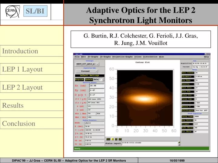
Adaptive Optics for the LEP 2 Synchrotron Light Monitors G. Burtin, R.J. Colchester, G. Ferioli, J.J. Gras, R. Jung, J.M. Vouillot Introduction LEP 1 Layout LEP 2 Layout Results Conclusion DIPAC’99 -- JJ Gras -- CERN SL/BI -- Adaptive Optics for the LEP 2 SR Monitors
Introduction: The Telescope Layout Layout of the Synchrotron Radiation Telescopes in LEP. Four Synchrotron Radiation telescopes are installed in LEP around IP8, two for each particle type, one located at the exit of the experimental straight section where the Dispersion is very small, the other in the arc where the Dispersion is large. DIPAC’99 -- JJ Gras -- CERN SL/BI -- Adaptive Optics for the LEP 2 SR Monitors
Introduction: The LEP 1 era. With a beam energy limited to 45 GeV we manage to control our telescopes with a relatively standard layout. DIPAC’99 -- JJ Gras -- CERN SL/BI -- Adaptive Optics for the LEP 2 SR Monitors
Introduction: The Challenging Problems of LEP 2 But above 80 GeV, side lobes and asymmetric defocusing started to appear, pointing to the expected cylindrical deformation of the Be mirror due to the power deposition of the SR. To solve this problem, a special set-up had to be made: ? The Adaptive Optics LEP 2 DIPAC’99 -- JJ Gras -- CERN SL/BI -- Adaptive Optics for the LEP 2 SR Monitors
LEP 1 Layout: The Basic Layout The Basic Layout • The Imaging Devices • - Light Extraction Mirror: • a 10 mm thick, 23x23 mm2 Be mirror. • - Spherical Imaging Mirror: • with a focal length of 4 m. • - X - Y Steering Mirror: • to align precisely the light with the bench. • The Acquiring Devices • - A Camera: • a normal CCD. • - A Linear Density Filter: • to match the light intensity to the detector sensitivity. • - Chromatic & Special Filters: • to control wavelength and polarisation components. DIPAC’99 -- JJ Gras -- CERN SL/BI -- Adaptive Optics for the LEP 2 SR Monitors
LEP 1 Layout: The Major Difficulty The major difficulty was the precise selection of the light source due to the large bending radius of LEP (3100 m) and its distance from the telescope (21 m). A slit has been implemented to control precisely the centre of the light origin and the longitudinal acceptance. By moving the slit, the whole acceptance defined by the extraction mirror can be explored. Telescope Horizontal Phase Space with Beam Trajectories, Extraction Mirror and Slit acceptance bands. (The axes are the horizontal machine axis x and the trajectory angle q) DIPAC’99 -- JJ Gras -- CERN SL/BI -- Adaptive Optics for the LEP 2 SR Monitors
LEP 1 Layout: The Applied Correction The telescopes have been optimised during the LEP 1 runs to provide the beam emittances with best precision (±0.1 nm in the vertical plane). • The correction applied to the measured size is: • s2REAL-H/V = s2MEAS-H/V - s2LA - s2D-H/V • Where w = the slit size and sXX represents broadening introduced by: • - sLA = kLA w - the longitudinal acceptance. • - sDH = kDHl /w- diffraction due to the slit uniform window limitation • - sDV = kDVl2/3 - SR diffraction • This correction currently represented around 10 % of the measured sigma in the horizontal plane and 35 % in the vertical. DIPAC’99 -- JJ Gras -- CERN SL/BI -- Adaptive Optics for the LEP 2 SR Monitors
LEP 1 Layout: The Tuning Application The Beuv Scan Tool kDV = 3.9± 0.1 kDH = 1.6± 0.2 kLA = 40 ± 10 sLA = kLA w sDH = kDHl /w Ability to measure vertical emittances smaller than 1nm to ±0.1nm DIPAC’99 -- JJ Gras -- CERN SL/BI -- Adaptive Optics for the LEP 2 SR Monitors
The LEP 2 Layout: The Final Layout • The Acquiring Devices • Mobile Camera • Density Filter • Additional Polarisation Filter • Filters • The Imaging Devices • Light Extraction Mirror • Deformable Mirror • Slit • Spherical Imaging Mirror Layout of the Synchrotron Radiation Telescopes in LEP. [LEP 2 Devices in Red] DIPAC’99 -- JJ Gras -- CERN SL/BI -- Adaptive Optics for the LEP 2 SR Monitors
LEP 2 Layout: The Polarisation Filter When LEP energy exceeded 80 GeV, side lobes appeared on the beam image explained by the combination of the remaining vertical polarisation component of the SR and the cylindrical deformation of the Be Mirror due to the power deposition of the SR. A dichroic sheet polariser having an extinction ratio of 1/4000 has been added to the original metallic polarisation filters in order to attenuate further these lobes. LEP 2 DIPAC’99 -- JJ Gras -- CERN SL/BI -- Adaptive Optics for the LEP 2 SR Monitors
LEP 2 Layout: The Mobile Camera Above 80 GeV, the beam image is also no longer focussed in the same location in H and V, due to this cylindrical deformation of the extraction mirror. Slit position scans clearly demonstrate this effect and a mobile camera has been introduced to be able to optimise the telescopes either for H or V measurements. Result of a Mobile Camera Scan done at 94.5 GeV with 2.4 mA showing the beam image focussed at different location in the horizontal and vertical planes. DIPAC’99 -- JJ Gras -- CERN SL/BI -- Adaptive Optics for the LEP 2 SR Monitors
E = 94.5 GeV - I = 1.8 mA E = 94.5 GeV- I = 1.2 mA LEP 2 Layout: The Mobile Camera Other Results of Mobile Camera Scans DIPAC’99 -- JJ Gras -- CERN SL/BI -- Adaptive Optics for the LEP 2 SR Monitors
LEP 2 Layout: The Deformable Mirror In order to focus both planes simultaneously and anticipate the LEP beam energy and current increase (towards 100 GeV with currents above 3 mA per beam), an cylindrically deformable mirror has been implemented to compensate the main deformation of the Be mirror. This outsourced model allows a cylindrical deformation from flat to a radius of curvature of 350 m allowing to correct up to 3 mA at 94.5 GeV. A home made mirror has been installed this year and should allow us to correct up to 2.8 mA at 100 GeV (with a minimum radius of 270 m). DIPAC’99 -- JJ Gras -- CERN SL/BI -- Adaptive Optics for the LEP 2 SR Monitors
LEP 2 Layout: The Deformable Mirror A series of measurements were made at different energies and it has been estimated that the radius follows a law of the type: R= 7.7 105 Ib-1.7 Eb-3 with the radius R in [m], the beam intensity Ib in [mA], and the beam energy Eb in [GeV] Curvature radius of the Be mirror as a function of beam current measured at 94.5 GeV DIPAC’99 -- JJ Gras -- CERN SL/BI -- Adaptive Optics for the LEP 2 SR Monitors
Results • In 1998, the LEP2 layout has been implemented in the electron telescopes and: • The Be mirror deformation law has been refined. • A software server has been developed to monitor every minute the beam energy and current and deform accordingly the mirror. • The polariser has been fine tuned to maximise the vertical polarisation attenuation. • The slit position has been adjusted to target the SR origin inside the corresponding bending magnet. • The slit width has been adjusted to 1 mm for a longitudinal acceptance of ± 40 cm. DIPAC’99 -- JJ Gras -- CERN SL/BI -- Adaptive Optics for the LEP 2 SR Monitors
Results • Under these conditions, both telescopes gave the same emittance, within the errors on the beta values. • The importance of the deformable mirrors is very well demonstrated below, where the same beam is imaged with and without deforming the mirror and filtering the vertical polarisation. DIPAC’99 -- JJ Gras -- CERN SL/BI -- Adaptive Optics for the LEP 2 SR Monitors
Conclusion For the 1999 run, all telescopes have been put in the LEP 2 configuration and a campaign to re-measure the correction coefficients will be undertaken. . It should be then possible to reach a 2.8 mA beam current at 100 GeV before having to move the camera which gives a correction capability of an additional 1 mA, close to the LEP limit. DIPAC’99 -- JJ Gras -- CERN SL/BI -- Adaptive Optics for the LEP 2 SR Monitors