Download

1 / 29
290 likes | 405 Views
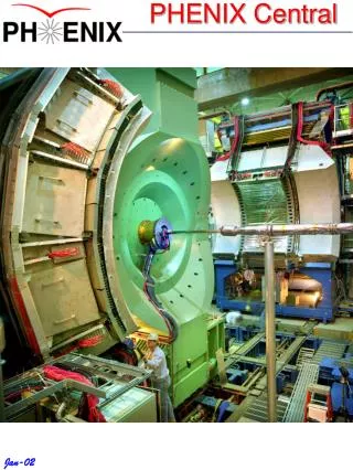
PHENIX Central Region. HBD. VTX. Integrate Detector Upgrades. From VTX Proposal (dims in mm). HYTEC Structural Results. GFRP sandwich composite M55J for the base structure substantial gain in the stiffness to weight ratio similar rad length and strength most widely used standard

E N D
PHENIX Central Region HBD VTX Integrate Detector Upgrades From VTX Proposal (dims in mm)
HYTEC Structural Results • GFRP sandwich composite M55J for the base structure • substantial gain in the stiffness to weight ratio • similar rad length and strength • most widely used standard • Outer frame structure should be single diameter • Structural end disks to prevent deformation of the structure under dynamic load inputs
HYTEC Cooling Results • Use ladder, or stave, concept supported at its ends by composite rings • Stave structure comprises a C-C thermal plane • OMEGA shaped composite bonded to back of thermal plane adds stiffness • Cooling tube bonded to the back of the C-C thermal plane with C-C tube support • Use Al cooling tubes 3mm in diameter supplied with a 23 g/s single-phase perfluorocarbon fluid, C5F12
VTX Spec Sheet For next round with HYTEC • Already consider barrel and endcaps • aid to visualizing integration • streamline engineering
Mechanical Engineering for VTX • Core design group assembled • PHENIX BNL Engineer D. Lynch: • Work on PHENIX central region, which includes VTX • Engineering specific to VTX being done at LANL by W. Sondheim & J. Boissevain • In consultation with PHENIX BNL engineer (off project) • Point of contact with HYTEC • D. Lee & R. Pak to provide oversight
Pretty Picture From J. Boissevain
Be Beam Pipe • Desirable to get as close as possible to collision vertex w/o adding considerable radiation length • In discussion w/: • PHENIX BNL Engineer (P. Kroon) • 0.3 +/- 0.1cm clearance between beam pipe and 1st Si layer to get VTX concentric with the beam • CAD Head of Vacuum Group (D. Hseuh) • 3cm diameter probably OK • Require NEG coating • AP Upgrades Coordinator (W. Fischer) • Physical aperture of at least 5 transverse rms beam sizes (allowing for 5mm orbit error) is OK
Off project Be Beam Pipe Quote
Mylar Sleeve • Proper grounding & isolation of Si detector • Image charge from circulating beam • Aluminized Mylar sleeve around Be beam pipe • Few mm’s thick to hold down material budget • Grounded w/ braid through magnet • No interference with other sub-systems; nothing else between beam pipe and 1st pixel layer
VTX Mechanical Support Structure • Frame for barrel & endcaps (HYTEC and LANL) • External support structure in central magnet (BNL) • Mechanical tolerances/distortions: • < 25 mm internally • 100 mm relative to the rest of the detector • From CAD Survey Group (F. Karl): • 50 – 100 mm on the bench • 100 – 200 mm in the hall
VTX Mech Support Structure (cont) • Clamshell Design: • Separates into two halves along the vertical axis • Modular Design: • Easily removable from IR • Allow for staged instrumentation • Mounted off of pole tips/nose cone calorimeter • To maintain specified tolerances
Routing for VTX Services Power, cooling and signal services are brought in at both ends, using the entire perimeter
VTX Auxiliary Systems • Services routed radially at the pole tips: • Power for Si detectors (proper grounding & isolation): • Si HV & LV power supplies • Cooling system for Si • Operating temperature: < 10o C • Improve signal/noise performance • Improve response to radiation dosage • Dry Air System • Bleed boil off from LN2 buggy into enclosure • Radiation Monitoring • TLDs & Chipmunks
Infrastructure for VTX • Electronics racks • Platforms above central magnet • Cooling for electronics • Power for auxiliary systems (proper grounding &isolation): • Clean & dirty power • 110V & 208V • UPS
Mechanical Structure Budget Based on HYTEC cost matrix
Closing Remarks • Additional people power: • PHENIX-BNL Operations Group has 8 FTE technicians and 3 FTE engineers • VTX project will have a number of postdocs & students participating in these tasks • CA Experiment Support Group provides at least one mechanical engineer plus trades people (carpenters, riggers and electricians)
VTX Design Criteria for HYTEC • Clamshell Design: • Separates into two halves along the vertical axis • Detector Coverage: • Hermeticity: single overlap circumferentially • 160o coverage in each half of barrel section • 4 layers of pixels and/or strip detectors in barrel section • 180o coverage in each half of the endcap sections • 4 layers of pixel detectors in endcap sections • +/- 40o Envelope maintained around barrel section • Endcap pixel disks, utilities, and barrel detector end support outside of envelope • Main clamshell support structure inside of envelope, but less than 0.5% radiation length (RL)
VTX Design Criteria for HYTEC (cont) • RL of 1% or less for each detector layer (includes: detectors, structure, and utilities) • Dimensional and structural stability of less than 25 µm for detectors and 100 µm gravitational structural stability of entire tracker • Utility Routing: • Along barrel end support for barrel region • Radial at pole tips for the end caps • Mounting of Tracker: • Off of magnet pole tips • Tracker to behave as a rigid body structure • Operating Temperature: Room temperature (or possibly 0o C)
HYTEC Cost Matrix Updated 1/14/05 <10 centigrade + 15 Staging Barrel/Endcap + 20 DOE Proposal R&D 2005
Methods: Contingency • Design/prototype/testing : 25% contingency each cycle • To cover cost risk that an extra pre-production cycle is needed • Last design/prototype/testing cycle : 50% contingency • Testing, assembly, and installation tasks: 50% contingency • Purchases based on vendor quotes: 25% contingency • Other purchases, 50% contingency
Methods: Overhead • All numbers quoted for manpower are fully loaded $ • Material costs include local overhead + sales-tax • Funds moved from BNL to other institutions charged 9% BNL admin. overhead