Download
1 / 135
1.35k likes | 1.49k Views
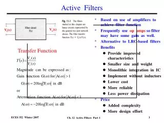
Design of High-Order Linear Transformation Active Filters. Presenter : 黃育賢 Yuh-Shyan Hwang Department of Electronic Engineering National Taipei University of Technology Date : 2008/03/26. Outline. 1.Introduction 2.Linear transformation method Voltage-mode Current-mode 3.Examples Gm-C

E N D
Design of High-Order Linear Transformation Active Filters Presenter :黃育賢 Yuh-Shyan Hwang Department of Electronic Engineering National Taipei University of Technology Date:2008/03/26
Outline • 1.Introduction • 2.Linear transformation method • Voltage-mode • Current-mode • 3.Examples • Gm-C • OTRA • CDBA、CDTA • DDCC 、 DCDDCC • 4.Conclusions
1. Introduction • Design of High-order active filters • Cascade topology • Follow-the-leader feedback
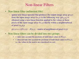
1. Introduction • Leap-Frog • Linear Transformation
2.Linear transformation method Voltage-mode Traditional two-port network Voltage-mode two-port network after linear transformation
2.Linear transformation method Voltage-mode Cross-cascade interconnection
2.Linear transformation method Current-mode Traditional two-port network Current-mode two-port network after linear transformation
2.Linear transformation method Current-mode Cross-cascade interconnection
3.Examples Gm-C Ideal Operational transconductance amplifier (OTA)
3.Examples Gm-C OTA schematic
3.Examples Gm-C Bias schematic Bandgapschematic
3.Examples Gm-C Voltage-mode Single-end output 3-order low-pass filter Voltage-mode Fully differential 3-order low-pass filter
3.Examples Gm-C (a) resisters;(b) non-resister Voltage-mode 3-order Butterworth Low-pass filter
3.Examples Gm-C gm1~gm7, gm9 OTA Vo/Vin voltage gain frequency response gm1~gm7, gm9 OTA frequency response Io/Vin
3.Examples Gm-C gm1~gm7, gm9 OTA Transient response gm8 OTA Voltage gain frequency response
3.Examples Gm-C gm8 OTA frequency response Io/Vin gm8 OTA Transient response
3.Examples Gm-C Filter frequency response Gain=-6.8dB,3dB bandwidth=229MHz Filter Transient response
3.Examples Gm-C Amplifier frequency response Gain=6.73dB,bandwidth=1.27GHz Bandwidth=1.1GMHz,gain=-0.37dB Voltage buffer frequency response
3.Examples Gm-C Gain=-0.52dB,3dB bandwidth=217MHz power consumption=9.77mW Full filter frequency response Full filter Transient response
3.Examples Gm-C THD
3.Examples Gm-C Specification
3.Examples Gm-C Voltage-mode 3-order Butterworth Low-pass filter layout
3.Examples Gm-C Current-mode Single-end output 3-order low-pass filter Current-mode Fully differential 3-order low-pass filter
3.Examples Gm-C Current-mode 3-order Butterworth Low-pass filter Current buffer
3.Examples Gm-C Bandwidth=8.5GHz gain=6.26dB Current buffer frequency response Gain=-0.157dB,3dB bandwidth=233MHz Power consumption=16.77mW Full filter frequency response
3.Examples Gm-C Transient response THD
3.Examples Gm-C Specification
3.Examples OTRA OTRA ideal model OTRA symbol & function
3.Examples OTRA OTRA schematic
3.Examples OTRA MOFET Resistor Circuit (MRC)
3.Examples OTRA Input stage
3.Examples OTRA Middle stage
3.Examples OTRA Output stage