Download
1 / 15
150 likes | 338 Views
Gamma-ray Large Area Space Telescope. GLAST Large Area Telescope: Tracker Subsystem MCM Production Readiness Review Mini-Tower Lessons Learned Robert Johnson Santa Cruz Institute for Particle Physics University of California at Santa Cruz Tracker Subsystem Manager rjohnson@scipp.ucsc.edu.

E N D
Gamma-ray Large Area Space Telescope GLAST Large Area Telescope: Tracker Subsystem MCM Production Readiness Review Mini-Tower Lessons Learned Robert Johnson Santa Cruz Institute for Particle Physics University of California at Santa Cruz Tracker Subsystem Manager rjohnson@scipp.ucsc.edu
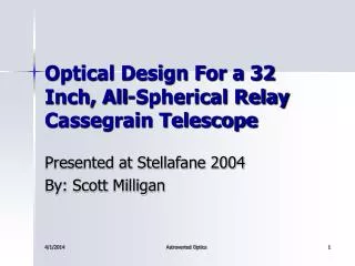
Tracker EM Mini-Tower 6 SSD planes read out by MCMs Initially outfitted with MCMs made in Jan ’03 with an earlier GTFE version and Nanonics connectors. Shown here with MCMs made in June ’03 using flight GTFE chips, V6 GTRC chips, and Omnetics connectors.
Lessons Learned • GTFE problems: shaping amplifier output bias was unstable, and there was too much delay in the configuration register readout. • Corrected in the flight design and verified with the Mini-Tower second iteration. • GTRC problems: a bug in the TOT algorithm caused DAQ timeouts, and the data readout timing gave insufficient margin at 20 MHz. • Corrected in the V7 GTRC and verified in tests at UCSC in the last two weeks. • Connector problems: • Nanonics connectors were very fragile and the jack screws easily stripped out. • Replaced with Omnetics connectors, which worked well in the Mini-Tower second iteration. • Omnetics connector issues and their resolution are discussed in a later presentation.
Lessons Learned • Bias short circuits: sharp fibers punctured the solder mask on the back of the MCM near the mounting holes, shorting the detector bias. • Replaced the solder mask in the design with Kapton. • Moved the bias circuit metal on the back of the board well away from the mounting holes and board edges. • The second Mini-Tower iteration had these improvements and had no problems with bias shorts. • High frequency of GTFE and GTRC die replacement • Much of the initial problem was due to the instability in the earlier chip design. • Improved the wafer test system to test 100% of the functionality and I/O at 20 MHz and implemented automated bad die marking. • Implemented Mil-Spec die inspection at the dicing vendor. • Still not perfect, but the latest set of 12 MCMs tested had only 1 die replaced out of 312 (0.3%).
Lessons Learned • Loss of bias connection. In the second Mini-Tower iteration there was at least one instance of the bias on the MCM not being connected to the pitch adapter (probably a wire bond failure). • Even in that case there was an intact redundant connection on the other side of the SSD ladder (set of 6 GTFE chips). • We improved the wire-bond process control (inspection, pull testing and plasma cleaning). • We doubled all bias wire bonds (side-by-side redundant bonds). • Flaking of encapsulation second layer. The Mini-Tower MCMs had the encapsulation applied in two steps (see next page), and in a couple of cases we observed the second application to flake off. • Dam added on the pitch-adapter side not only guarantees the new stay clear but also allows coverage of the wire bonds in a single application of the encapsulation epoxy.
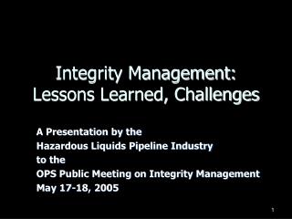
Encapsulation Improvement Encapsulation had been improved with a dam along the pitch adapter, which allows wire bonds to be covered in one application.
Lessons Learned • Loss of signal connection to the front-end chips. • Improved wire-bond process control (pull testing, inspection, and plasma cleaning) greatly reduces the chance of losing a wire bond during encapsulation. • Increased flex-circuit bend radius (from 0.64mm to 1.0mm) and smoother transitions in the machining appear to have eliminated cracking of traces. • (Earlier problems with trace cracking due to a cover layer and glass beads in the adhesive were fixed in the second Mini-Tower iteration.) • We have probed one by one all traces on 4 preproduction MCMs and have found zero broken connections in 6,144 channels, even after thermal cycling and burn-in. More tests are in progress. • Difficulty in making a ground connection on the Mini-Tower MCMs. The grounding holes were covered by conformal coating. • We now specify those areas to be masked before applying the conformal coating.
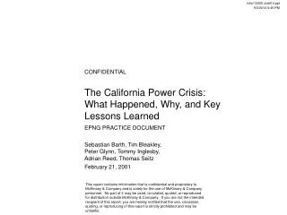
Lessons Learned • Pitch-adapter pitch. The Mini-Tower pitch adapters were longer than designed, and the flight Parlex pitch adapters tend to be shorter than design. Too long is especially bad, as it puts the bias traces too close to the end of the PWB. Either long or short is bad from the point of view of having an indeterminate pitch for wire bonding. • We have implemented at SLAC a screening of the Parlex circuits, to reject circuits that are shrunk by more than 100 microns and to reject circuits for which the the distance across one ladder deviates from nominal by more than 30 microns. Mini-Tower MCM with the bias trace too close to the end.
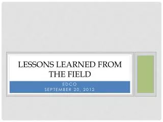
Lessons Learned • Pitch-adapter alignment. In Italy they will have only a small range of adjustment to align the MCM with the bias circuit and SSDs. Too much offset results in wire bonds crossing over each other. • This problem tends to correlate with the pitch-adapter shrinkage (see the next page). • We implemented in our flex-attach inspection a requirement that the offset be no more than one trace width (about 200 microns).
SN 173 Fixture 2 SN 184 Fixture 1
Lessons Learned • Flex-circuit voids and debonding. G&A cannot wire bond to traces that are not firmly glued down. • All edges and corners are visually inspected (twice) for debonding or peeling before mounting any EEE parts. • A new epoxy vendor and mixing method has been found to eliminate bubbles and is being tested now (preproduction epoxy was centrifuged to improve the epoxy that we had available). Mini-Tower MCM with a debonded region of flex circuit.
Lessons Learned • Trimming of the flex-circuit ends. Some Mini-Tower MCMs flex-circuit and/or glue extended beyond the stay clear and interfered with the tray structure. Trimming the flex after bonding risked causing debonding and peeling. • We will use a go-no-go gauge in the flight production to verify the stay clear. • The flex now is trimmed with a die cutter before bonding. This gave excellent results in the preproduction. Mini-Tower MCM with the flex-circuit extending beyond the stay clear.
Lessons Learned • Poor flex-circuit trimming along the Italian edge. In the Mini-Tower MCMs, the flex was cut too far inward, damaging the PWB and reducing the wire bonding area, or too far outward, resulting in the flex being pulled over the edge, cracking traces. • The flex-circuit now is trimmed cold, which works much better than when trimmed still hot from the oven. • The cutting jig was adjusted to work well with the new PWBs. • These problems are now looked for in the visual inspection. Mini-Tower MCM with the flex trimmed too far inward from the Italian edge. Mini-Tower MCM with the flex trimmed too far outware from the Italian edge.
Lessons Learned • Formation and machining of the raised right-angle interconnect on the PWB. For the 2nd Mini-Tower iteration we tried to have the entire process done by one vendor, DDI. They did a terrible job of aligning and gluing the raised strip and a worse job of machining the radius. The result negatively affected the flex-attach process. • We developed a precision process with DDI to form the raised strip using a second, aligned panel, and they changed from a PSA to an acrylic adhesive. • We moved the precision machining to height and machining of the radius to a machine shop (Holt Machining), followed by CMM inspection at SLAC. The results are within or close to the goal of 50 microns along the entire edge. • We increased the radius to 1.0 mm and made a custom tool that allows the radius to be machined without discontinuities that would kink the copper traces.
Lessons Learned In Addition, the Preproduction MCMs incorporated all the following process improvements relative to what was done for the Mini-Tower MCMs: • Introduced all flight-quality procedures at Teledyne, as well as formal procedures for travelers, NCRs, waivers, and EIDP. • All customer supplied parts are now those intended for flight. See a later presentation regarding the qualification status of all parts. • Implemented more thorough electrical testing, through continued development of that procedure. • Implemented the thermal-cycling, burn-in, and final acceptance test processes (see a later presentation).