Download
1 / 22
250 likes | 1.01k Views
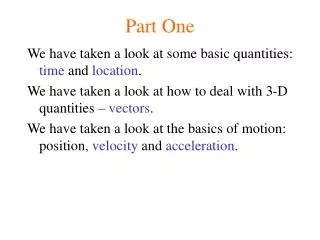
Power System Protective Relaying-Part One. Wei-Jen Lee, Ph.D., PE Professor of Electrical Engineering Dept. The Univ. of Texas at Arlington Tel: 817-272-5046 E-mail: lee@exchange.uta.edu. Introduction. Nature Cause. Introduction. Equipment Failure. Introduction. Human Error.

E N D
Power System Protective Relaying-Part One Wei-Jen Lee, Ph.D., PE Professor of Electrical Engineering Dept. The Univ. of Texas at Arlington Tel: 817-272-5046 E-mail: lee@exchange.uta.edu
Introduction • Nature Cause
Introduction • Equipment Failure
Introduction • Human Error
Introduction • Relay:an electric device that is designed to respond to input conditions in a prescribed manner and , after specified conditions are met, to cause contact operation or similar abrupt change in associated electric control circuits. (IEEE)
Introduction • Protective Relay:A relay whose function is to detect defective lines or apparatus or other power system conditions of an abnormal or dangerous nature and to initiate appropriate control circuit action. (IEEE)
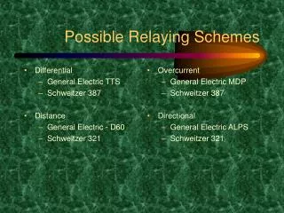
Sample Device Numbers • Master element: 1 • Time-delay starting or closing relay: 2 • Distance relay: 21 • Directional power relay: 32 • Instantaneous overcurrent relay: 50 • AC time overcurrent relay: 51 • AC directional overcurrent relay: 67 • Frequency relay: 81 • Differential protective relay: 87
Typical Relay and Circuit Breaker Connections • Typical single line AC connection
Typical Relay and Circuit Breaker Connections • Typical three-phase AC connection
Basic Objectives of System Protection • Reliability • Selectivity • Speed of Operation • Simplicity • Economics
Factors Affecting the Protection System • Economics • Personality • Location of Disconnecting and Input Devices • Available Fault Indicators
Classification of Relays • Protective Relays • Regulating Relays • Reclosing, Synchronism Check, and Synchronizing Relays • Monitoring Relays • Auxiliary Relays • Others
Protective Relay Performance • Since many relays near the trouble area may begin to operate for any given fault, it is difficult to completely evaluate an individual relay’s performance. • Performance can be categorized as follows: • Correct: (a) As planned or (b) Not as planned or expected. • Incorrect: (a) Fail to trip or (b) False tripping • No conclusion
Principles of Relay Application • The power system is divided into protection zones defined by the equipment and available circuit breakers. Six possible protection zones are listed below: • Generators and generator-transformer units • Transformers • Buses • Lines (Transmission, subtransmission, and distribution) • Utilization equipment • Capacitor or reactor banks
Principles of Relay Application • Typical relay primary protection zones
Principles of Relay Application • Overlapping protection zones
Information for Application • One line diagram and system configuration • Impedance and connection of the power equipment, system frequency, system voltage, and system phase sequence • Existing protection and problems • Operating procedure and Practices • Importance of the system equipment being protected
Information for Application • System fault study • Maximum loads and system swing limits • Current and voltage transformer locations, connections, and ratios • Future expansion