Download
1 / 127
1.34k likes | 2.08k Views
Control of Sulfur Oxides. 朱信 Hsin Chu Professor Dept. of Environmental Engineering National Cheng Kung University.

E N D
Control of Sulfur Oxides 朱信 Hsin Chu Professor Dept. of Environmental Engineering National Cheng Kung University
This chapter and the next concern pollutants-sulfur oxides and nitrogen oxides-cannot be economically collected by physical means nor rendered harmless by combustion as the control of particulates and VOCs. • Their control is largely chemical rather than physical.
SO2, SO3, and NO2 are strong respiratory irritants that can cause health damage at high concentrations. • These gases also form secondary particles in the atmosphere. • They are the principal causes of acid rain.
1. The Elementary Oxidation-Reduction Chemistry of Sulfur and Nitrogen • The sources and control methods are significantly different for sulfur oxides and nitrogen oxides, but their chemistry is quite similar. • Table 11.1 (next slide) shows the oxidation and reduction products of nitrogen and sulfur.
Both hydrogen sulfide and ammonia are very strong-smelling substances, gaseous at room temperature (-60oC and -33oC boiling points, respectively), and toxic in high concentrations. • NO, NO2, SO2, and SO3 are all gases at room temperature or slightly above room temperature (boiling points 21oC, 34oC, -10oC, and 45oC, respectively). • The estimated concentrations of these materials in unpolluted parts of the world’s atmosphere are SO2, 0.2 ppb; NH3, 10 ppb; NO2, 1 ppb.
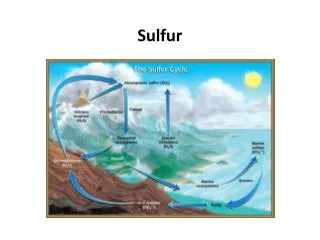
2. An Overview of the Sulfur Problem • Fig. 11.1 (next slide) shows in part how sulfur moves in the environment as a result of human activities.
Sulfur is the sixteenth-most abundant element in the earth’s crust, with an abundance of about 260 ppm. • The vast majority of this sulfur exists in the form of sulfates, mostly as gypsum, CaSO4•2H2O, or anhydrite, CaSO4.
All organic fuels used by humans (oil, coal, natural gas, peat, wood, others) contain some sulfur. • Fuels like wood have very little (0.1% or less), whereas most coals have 0.5% to 3%. • Oils generally have more sulfur than wood but less than coal.
If we burn the fuels, the contained sulfur will mostly form sulfur dioxide: • If we wish to prevent this SO2 from getting into the atmosphere, we can use any of the methods described in this chapter, all of which have the effect of capturing the sulfur dioxide in the form of CaSO2•2H2O that will then be returned to the earth, normally in a landfill.
Most often the overall reaction will be • In natural gas most of the sulfur is in the form of H2S, which is easily separated from the other constituents of the gas.
In oil and also in oil shales and tar sands, the sulfur is chemically combined with the hydrocarbon compounds; normally it cannot be removed without breaking chemical bonds. • In oils the sulfur is concentrated in the higher-boiling fraction of the oil, so the same crude oil can yield a low-sulfur gasoline (average 0.03% S) and high-sulfur heavy fuel oil (e.g., 0.5% to 1% S).
In coal much of the sulfur is also in the form of chemically bound sulfur, but some coals have a large fraction of their sulfur in the form of small (typically 100µ) crystals of iron pyrite (fools gold, FeS2). • When the fuel is burned, almost all of the sulfur in the fuel is converted to SO2. • Some small fraction is captured in the ash, and some is converted to SO3.
Mixtures of SO2 and SO3 are sometimes called SOX. • The other important source of SO2 attributable to humans is the processing of sulfur-bearing ores. • The principal copper ore of the world is chalcopyrite, CuFeS2.
The basic scheme for obtaining copper from it is the overall high-temperature smelting reaction:CuFeS2 + 2.5 O2→ Cu + FeO + 2 SO2 (2) • The principal ores of lead, zinc, and nickel are also sulfides, whose processing is similar to above reaction. • Table 11.2 (next slide) shows the emission sources for SO2 in the U.S. in 1997.
The sulfur-containing gas streams most often dealt with in industry belong to three categories-reduced sulfur, concentrated SO2 streams, and dilute SO2 streams-each with its own control method.
3. The Removal of Reduced Sulfur Compounds from Petroleum, Natural Gas Streams, and Fuel Gases of Coal Gasification Example 1 • A flow of 108 scf per day (32.8 sm3/s) of natural gas (≈ 0.2% of average U.S. consumption), which contains 1% (10,000 ppm) of H2S, is treated in the apparatus sketched in Fig. 10.15 (absorption –stripping) to reduce the H2S concentration to 4 ppm (the maximum allowed in commercial natural gas in the U.S.).
The gas is scrubbed at a pressure of 100 atm and 20oC. Assuming that we will use water as the scrubbing agent, estimate the required water flow rate. • Solution:From a handbook we find the Henry’s law constant for H2S at 20oC = 483 atm, so
As in Example 14 of last chapter, we arbitrarily specify that the outlet liquid shall have yi* = 0.8 yi. • Thus we can calculate that xibottom = 0.8 0.207 0.01 = 1.66 10-3 (mol fraction )
The molar flow rate of gas is • So the required liquid flow rate is • This is a large liquid flow rate, one must find a solvent that can absorb much more H2S than can the water in this example.
H2S, SO2, SO3, NO2, HCl, and CO2 are acid gases, which form acids by dissolving in water. For H2S the process is • If we can add something to the scrubbing solution that will consume either the H+ or the HS-, then more H2S can dissolve in the water, and much less water is needed.
For acid gases, the obvious choice is some alkali, a source of OH- that can remove the H+ by: • Removing the H+ on the right side of Eq. (3) drives the equilibrium to the right, greatly increasing the amount of H2S absorbed.
If the solution is to be regenerated in the rightmost column in Fig. 10.15, then the alkali should be a weak alkali that can easily give back the acid gas on heating or pressure reduction. • If only the leftmost column of Fig. 10.15 is used and the resulting solution is discarded, then a strong alkali, which could not be easily regenerated, can be used.
The most common choices of alkali for H2S removal are ethanolamines (monoethanolamine, diethanolamine, and triethanoamine) and also the sodium or potassium salts of weak acids like carbonic or phosphoric.
Example 2 • Repeat Example 1, using as the absorbent a 2N (12.2 wt%, 3.94 mol%) solution of monoethanolamine (MEA), HO(CH2)2NH2, as the scrubbing solution, at 77oF = 25oC. • Solution:For this solution strength and temperature, Kohl and Nielsen give a plot of pi = Pyi* as a function of mols H2S per mol of MEA that can be approximated by:
Following Example 1, we choose the outlet liquid concentration to have yi* = 0.8 yi and solve Eq. (4) for the corresponding x, finding • If we also require that at the top of the column yi* = 0.8 yi, we can compute the maximum permitted concentration of H2S in the regenerated solution as:
and • The required liquid flow rate is that in Example 1 multiplied by (0.0250/6.04) = 0.041, or 13.5 lb/s = 6.1 kg/s. #
3.1 The Uses and Limitations of Absorbers and Strippers for Air Pollution Control • The system in Fig. 10.15 also works extremely well for removing ammonia or SO2 from a gas stream. • NO and NO2 are not readily removed from gas streams by the process shown in Fig. 10.15.
Although NO2 is an acid gas that produces nitric acid by reaction with water:the reaction rate is slow. • NO is not an acid gas, so that although we can remove NO2 from a gas stream with an alkaline solvent, we cannot remove NO with the same solvent.
3.2 Sulfur Removal from Hydrocarbons • Once H2S has been separated from the other components of the gas, it is normally reacted with oxygen from the air in controlled amounts to oxidize it only as far as elemental sulfur (the Claus process):H2S = ½ O2→ S + H2O • Sulfur in hydrocarbon fuels is normally converted to SO2 during combustion and then emitted to the atmosphere.
Large oil-burning facilities can have equipment to capture that SO2, but autos, trucks, and airplanes do not. • The only way to limit the SO2 emissions from these sources is to limit the amount of sulfur in the fuel. • Most of that sulfur is removed by catalytic hydrodesulfurization:
The mixture leaving the reactor is cooled, condensing most of the hydrocarbons. • The remaining gas stream, a mixture of H2 and H2S, is one of the streams treated in a refinery for H2S removal by the process shown in Fig. 10.15.
4. Removal of SO2 from Rich Waste Gases • The SO2 concentrations in off-gases from the smelting of metal sulfide ores depend on which process is used and vary with time within the batch smelting cycle. • However, they generally range from 2% to 40% SO2. • Such gases can be economically treated in plants that produce sulfuric acid by the following reactions:
Example 3 • One of the largest copper smelters in the U.S. produces 320,000 tons of copper per year. The coppor ore smelted is principally chalcopyrite. • If all the sulfur were emitted to the atmosphere as SO2, how much would be emitted? • If all the sulfur in the ore were converted to sulfuric acid, how much sulfuric acid per year would that smelter produce?
Solution:From Eq. (2) we know that we would expect to produce 2 mols of SO2 per mol of copper. • The molecular weights are 64 for SO2 and 63 for copper, so we would expect to produce 320,000 ton/yr (2 64/63) = 650,000 ton/yr of SO2. • If this were all converted to H2SO4 (MW = 98), it would be 650,000 ton/yr (98/64) = 996,000 ton/yr. #
Eq. (5) is an equilibrium reaction, which does not go to completion. • Furthermore, this reaction is exothermic, so that the percent conversion at equilibrium is higher at low temperatures than at high temperatures. • For this reason the reaction is customarily carried out in three or four separate catalyst beds with intercoolers between them. • The course of the reaction is shown in Fig. 11.2 (next slide).
From Fig. 11.2, about 98% of the incoming SO2 can be converted to H2SO4. • In a simple acid plant, the remaining 2% of the SO2 is vented to atmosphere. • In response to legal pressure to reduce this SO2 emission, plants have been developed that are, in effect, two plants in series, as shown in Fig. 11.3 (next slide).
Comparing this flow diagram to Fig. 10.15, we see an SO3 absorber but no stripper. • There is no need to regenerate the absorbing liquid, because the solution of SO3 in water, H2SO4, is the saleable product. • The Henry’s law constant for SO3 in water at 20oC is roughly 10-25 atmosphere, so this absorption is very rapid and easy.
A limitation is that production of H2SO4 is uneconomic when the concentration of SO2 in the waste gas is too low. • Most analysts believe that with SO2 concentrations more than 4%, the acid plant can show a profit if there is a nearby market for the acid.
5. Removal of SO2 from Lean Waste Gases • The major source of SO2 is the stacks of large coal- or oil-burning facilities. • For them, the typical SO2 content of the exhaust gas is about 0.1% SO2, or 1000 ppm, which is much too low for profitable recovery as H2SO4.
The most widely used procedure for controlling SO2 emissions from these sources is scrubbing with water containing finely ground limestone; the overall effect is shown by Eq. (1). • The whole process is called flue gas desulphurization, and the acronym FGD is widely used.
Example 4 • A power plant produces 106 scfm (472 sm3/s) of exhaust gas with 0.1% SO2. • We are required to remove 90% of it before the gas is discharged into the atmosphere. • We propose to do so by dissolving the gas in Fig. 10.15. • How large a flow of water will be needed if we make the same requirement as in Example 1, that at the bottom of the absorber yi* = 0.8yi?
Solution:This situation is clearly similar to Example 1. However, here the Henry’s law constant for SO2 is much smaller, 9 atm, leading to a greater solubility. • The pressure is 1 atm instead of 100 atm. • The outlet liquid will have the following characteristics:
As we saw in Example 2, the amount of scrubbing water required can be substantially reduced if we add a regent to the water that increases the solubility of the gas being removed. Example 5 • The power plant in Example 4 wishes to remove 90% of the SO2 by scrubbing the exhaust gas with a dilute solution of sodium hydroxide, NaOH. • How much NaOH will they need? What problems will they encounter?
Solution:The overall reaction (including the oxidation of sulfite to sulfate) will be:2NaOH + SO2 + ½ O2 → Na2SO4 + H2O (7) • From Example 4, we know that we must remove (0.9)(0.001)(43.3 lb mol/s) = 0.039 (lbmol/s) of SO2. • Therefore, we will need, as a minimum, 2(0.039) = 0.078 lbmol/s of NaOH.