Download
1 / 24
270 likes | 512 Views
Control of sulfur oxide. Control of sulfur oxide. 低硫燃料 燃料脫硫 排煙脫硫. 加氫脫硫. Schematic diagram of a typical Hydrodesulfurization (HDS) unit in a petroleum refinery. Source: http://en.wikipedia.org/wiki/Hydrodesulfurization. Amine gas treating.

E N D
Control of sulfur oxide • 低硫燃料 • 燃料脫硫 • 排煙脫硫
加氫脫硫 Schematic diagram of a typical Hydrodesulfurization (HDS) unit in a petroleum refinery Source: http://en.wikipedia.org/wiki/Hydrodesulfurization
Amine gas treating • Amine gas treating, also known as gas sweeteningand acid gas removal, refers to a group of processes that use aqueous solutions of various alkylamines (commonly referred to simply as amines) to remove hydrogen sulfide (H2S) and carbon dioxide (CO2) from gases. • Many different amines are used in gas treating: • Diethanolamine (DEA) • Monoethanolamine (MEA) • Methyldiethanolamine (MDEA) • Diisopropanolamine (DIPA) • Aminoethoxyethanol (Diglycolamine) (DGA) • The most commonly used amines in industrial plants are the alkanolamines DEA, MEA, and MDEA. Source: http://en.wikipedia.org/wiki/Amine_gas_treating
Process flow diagram of a typical amine treating process used in petroleum refineries, natural gas processing plants and other industrial facilities. Source: http://en.wikipedia.org/wiki/Amine_gas_treating
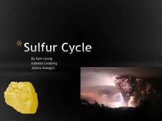
Claus Process The Claus technology can be divided into two process steps, thermal and catalytic. Thermal step The overall equation is 10 H2S + 5 O2 → 2 H2S + SO2 + 7/2 S2 + 8 H2O This equation shows that in the thermal step alone two-thirds of the hydrogen sulfide is converted to sulfur. Catalytic step 2 H2S + SO2 → 3 S + 2 H2O (ΔH = -1165.6 kJ mol-1)
Schematic flow diagram of a straight-through, 3 reactor (converter), Claus sulfur recovery unit. Source: http://en.wikipedia.org/wiki/Claus_process
Integrated Gasification Combined Cycle (IGCC) • An integrated gasification combined cycle (IGCC) is a technology that uses a gasifier to turn coal and other carbon based fuels into gas—synthesis gas (syngas). • It then removes impurities from the syngasbefore it is combusted. Some of these pollutants, such as sulfur, can be turned into re-usable byproducts. This results in lower emissions of sulfur dioxide, particulates, and mercury. • With additional process equipment, the carbon in the syngas can be shifted to hydrogen via the water-gas shift reaction, resulting in nearly carbon free fuel. The resulting carbon dioxide from the shift reaction can be compressed and stored. • Excess heat from the primary combustion and syngas fired generation is then passed to a steam cycle, similar to a combined cycle gas turbine. This results in improved efficiency compared to conventional pulverized coal. Source: http://en.wikipedia.org/wiki/Integrated_gasification_combined_cycle
Coal gasification • Coal gasificationis the process of producing syngas–a mixture consisting primarily of carbon monoxide (CO), hydrogen (H2), carbon dioxide (CO2) and water vapor (H2O)–from coal and water, air and/or oxygen. 3C (i.e., coal) + O2 + H2O → H2 + 3CO • The coal gas undergoes the water gas shift reaction where more hydrogen is produced by additional reaction with water vapor: CO + H2O → CO2 + H2
Source: http://en.wikipedia.org/wiki/Integrated_gasification_combined_cycle
Integrated Gasification Combined Cycle (IGCC) Source: MIT, 2007, The future of coal
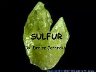
Lime Scrubbing Process Chemistry Lime scrubbing uses an alkaline slurry made by adding lime (CaO), usually 90% pure, to water. The alkaline slurry is sprayed in the absorber and reacts with the SO2 in the flue gas. Insoluble calcium sulfite (CaSO3) and calcium sulfate (CaSO4) salts are formed in the chemical reaction that occurs in the scrubber and are removed as sludge. A number of reactions take place in the absorber. Before the calcium can react with the SO2, both must be broken down into their respective ions. This is accomplished by slaking (dissolving) the lime in water and then spraying the slurry into the flue gas to dissolve the SO2. Simplified reactions occur simultaneously and are illustrated below. Source: USEPA, APTI, si412c, lesson 9
Limestone Scrubbing Process Chemistry Limestone scrubbers are very similar to lime scrubbers. The use of limestone (CaCO3) instead of lime requires different feed preparation equipment and higher liquid-to-gas ratios (since limestone is less reactive than lime). Even with these differences, the processes are so similar that an FGD system can be set up to use either lime or limestone in the scrubbing liquid. The basic chemical reactions occurring in the limestone process are very similar to those in the lime-scrubbing process. The only difference is in the dissolution reaction that generates the calcium ion. When limestone is mixed with water, the following reaction occurs: The other reactions are the same as those for lime scrubbing. Source: USEPA, APTI, si412c, lesson 9
In forced oxidation, air is blown into a designated section of the absorber module or into a separate reaction (oxidation) tank. The air oxidizes the calcium sulfite to calcium sulfate in the following reaction: CaSO3 + H2O + 1/2 O2 → CaSO4 + H2O Figure source: http://en.wikipedia.org/wiki/Flue-gas_desulfurization
Dual-Alkali Scrubbing Process Chemistry The sodium alkali solution is usually a mixture of the following compounds: 1. Sodium hydroxide (NaOH), also called caustic 2. Sodium carbonate (Na2CO3), also called soda ash 3. Sodium sulfite (Na2SO3) Source: USEPA, APTI, si412c, lesson 9