Download
1 / 46
630 likes | 1k Views
Total Lightning Detection. Your Name & Affiliation. Why Use Lightning Information?. Lightning data is real-time, no delays! Lightning assists in routing aircraft around storms. It is absolutely necessary for safety during ground operations--refueling and other aircraft preparations.

E N D
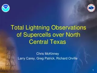
Total Lightning Detection Your Name & Affiliation
Why Use Lightning Information? • Lightning data is real-time, no delays! • Lightning assists in routing aircraft around storms. • It is absolutely necessary for safety during ground operations--refueling and other aircraft preparations. • Lightning is a valuable meteorological data source that enhances other sources such as weather radar. • Lightning information covers a large area, even extending out to the ocean. • Lightning information is very economical.
AFWA’s Current NLDN Lightning Data Stream • Cloud-to-ground (CG) data only • But…a large percentage of lightning occurs in cloud (IC) • IC often precedes CG by 5-20 min • Research shows IC + CG is better indicator of storm severity than CG alone • IC + CG is now available at reasonable price
Three Lightning Detection Technologies LF/VLF ground wave (NLDN) VLF reflected between ground and ionosphere (long-range network) VHF line-of-sight only (SAFIR, LDAR II, LS8000)
CG Lightning Detection--LF • C-G lightning typically detected in the LF range. • Longer detection range. • Ability to locate ground strike point with high accuracy. • Ability to determine lightning polarity and peak current. • Some ability to differentiate between C-G and cloud lightning. • C-G lightning has a fingerprint detected in its waveform. • C-G lightning is located using one of these methods. Time of Arrival (TOA) Magnetic Direction Finding (MDF)
Total Lightning (IC+CG) Detection-VHF LDAR-II & LMA TOA Systems Small areal coverage Large number of sensors required 3-D displays are good But…Too expensive---few networks exist LMA – New Mexico Tech (VHF TOA) LDAR-II Vaisala (VHF TOA) – Not on the market LS 8000 Vaisala Interferometry System WTLN WeatherBug (Broadband TOA system)
T.O.A. Interferometry d d d d dT ~100µs ~9ns VHF Interferometry---a Timing Measurement Technique • The two most common methods of locating lightning in the VHF range are Time-of-Arrival and Interferometry. • Interferometry consists of measuring the time difference between closely spaced antennas. The main difference with Time-of-Arrival is that it operates on continuous waves and not individual pulses. • The accuracy is achieved by integrating a very large number of periods (typically 11 000 for each measurement)
The Vaisala LS Series Lightning Detection SystemCG + IC = Total Lightning
LS8000 Sensor – Total Lightning Detection • Technology: • VHF Interferometry combined with LF Time of Arrival (TOA) and Magnetic Direction Finding (MDF) • VHF for 2-D cloud lightning mapping • LF for accurate CG detection (as in NLDN) • Benefits: • Longer baseline network (fewer sensors) to cover same area as VHF-TOA (LDAR II) • Accurate LF CG data, improvements to 250 meter Location Accuracy • Lower overall cost of ownership
The LS8000 Sensor • The 5 dipole antenna VHF interferometry system locates cloud discharges with a high level of accuracy • The LF antenna from the gives detailed CG information • Combining the two gives a clear picture of total lightning and mapping the full spatial extent of flashes
Notes ● Interferometry allows longer baselines between sensors (larger areal coverage) and increased accuracy compared to other VHF total lightning systems. ● Proper sensor siting is critical…must have clean horizon. ● Cloud must have active discharges to be detected. ● The LS8000 is not a 3-D system…only 2-D.
You See Paths of All Flashes • Detects over 90% of all cloud lightning and CG lightning • Maps the spatial extent of both cloud and the in-cloud portion of CG flashes
End Start Some Cloud Flashes are Very Long • 13 October 2001 North Texas • Cloud flash was ~190 km long (from ~ Waco to Dallas, TX). • It put down two CG flashes along the way (white symbols)
IC (red) and CG flashes (black) between 0312:30 - 0317:30 UTC 15 June 2001 Fort Worth WSR-88D base reflectivity from 0315 UTC 15 June 2001 Isolated CG Lightning Threat Quiz--Where is Lightning Threat?Not just where CG is occurring High CG Lightning Threat High CG Lightning Threat IC flashes cover much larger area than CG flashes—the threat area is much larger than where CG occurs.
Can radar alone provide sufficient information to assess lightning data? Does the KDFW box have a lightning threat ? Imminent CG threat? 24 April 2008
No!! Note VHF total lightning perspective IC lightning already occurring 24 April 2008
Total lightning perspective 3 CG flashes on edge of box—far away from main lightning region 24 April 2008
Example 2 – Radar PerspectiveDo both boxes have a lightning threat? 07 - 08 UTC 6 November 2006 movie
NLDN CG Lightning Perspective CG but no dBZ 07 - 08 UTC 6 November 2006
VHF Total Lightning Perspective IC but no dBZ 07 - 08 UTC 6 November 2006 movie
Example 3Go to animation! Tucson Total Lightning NetworkJuly 26, 2008
Tucson LS8000 NetworkIC precedes CG & IC threat persists in CG lull Cloud flash precede CG strokes Cloud flash and CG stroke rates for a severe thunderstorm11 August 2007 Hail Wind
Aviation Applications, Turbulence Identification Only LS8000 can identify anvil regions Identification of turbulence within thunderstorm cores Identification of turbulence within thunderstorm anvils
The Lightning Detection Network 1 – Vaisala Thunderstorm Sensor 2 – TLP™ central processor 3 – Real-time Displays
Building an LS8000 Network • Sites must be carefully selected: • Distance between sensors: 100 to 150 km for an Interferometric network • Sensors should be in “Triangle strips” • Each sensor should have an optimal Field of View---No far obstacles • Antenna surroundings should be as clean as possible---No close obstacles • Sites should be free of strong radio sources • Noise floor should be as low as possible • Power and communication should be easily available • Site should be accessible (installation and maintenance)
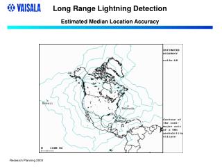
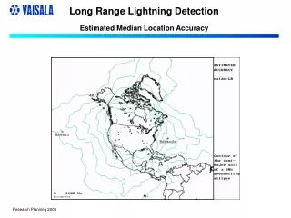
Building a VHF Network • Interferometric Network • Location Accuracy for a full network of sensors, about 100 km apart. Location accuracy is better than 1 km almost everywhere
VHF Site Projections Cloud Flash DE % 7 sensors at: • ABY • OZR • EVX • AQQ • VAD • CTY • TLH Benning Rucker Moody > 90% Hurlburt Tyndall Six military installations receive excellent coverage with this network
CG Flash Detection Efficiency % > 90% in all 6 military areas Benning Rucker Moody Hurlburt Tyndall
CG Stroke Location Accuracy (km) • < 0.5 km over land
Collaborations • Florida State University has been researching the operational use of lightning data for many years. • They would like to receive the data and work with us to use the data to maximum advantage. • This would involve visits, seminars, etc. to DOD facilities.
Vaisala LS8000 Total Lightning Network Cost Estimates • A network of 7 LS8000 Sensors • LTS viewing software and hardware • Includes sensor installations, masts, and communications equipment and fees • Hardware and software located at: HRT; AQQ; CTY; OZR; ABY; TLH; VAD
Cost Estimates • Scenario 1: Government owned network / Vaisala managed • USAF purchases: • The 7 LS8000 sensors and required mounting hardware • LTS viewing software and hardware • ~$716K for Vaisala equipment (one time charge) • USAF responsible for civil works and sensor maintenance / repair • Vaisala will provide: • Communications equipment • Installation of all equipment and sensors • Training on LS8000 sensors and LTS viewing software • Annual 24/7 network data processing with TLP processor, monitoring, quality control of data, data archiving, and be responsible for communications. • Make this data available to each of the locations via TCP/IP • ~$220K annual fee • Total cost year one: $936K / Year two ~$220K
Cost Estimates • Scenario 2: Vaisala owned and operated network • Total ‘turn key’. Vaisala will conduct site surveys, complete civil works, install 7 LS8000 sensors, communications equipment, 7 LTS viewing software displays with hardware, train operators on the use of LTS and be responsible for all aspects of 24/7 monitoring, quality control reporting, data archiving, and up time reports. • Vaisala will make this data available to each of the locations. • Annual fee: ~$515K/yr