Download
1 / 29
330 likes | 689 Views
Basis for Color in Transition Metal (TM) Complexes. Crystal (really “Ligand”) Field Theory. Goals. Learn that when ligands bind to a metal complex, the d orbital sublevel becomes further “split” into sub-sublevels

E N D
Basis for Color in Transition Metal (TM) Complexes Crystal (really “Ligand”) Field Theory Ppt07(PS11)
Goals • Learn that when ligands bind to a metal complex, the d orbital sublevel becomes further “split” into sub-sublevels • Electronic transitions between these sub-sublevels absorb visible light, causing “color” • Learn what is meant by “strong field” and “weak field” cases, and how these impact the electron configuration (and paramagnetism). • Use these ideas to explain why different complexes of the same TM cation have different colors (ruby vs emerald) Ppt07(PS11)
Review, electron configurations for TM cations (& # d electrons) • Earlier (self study worksheet or exercise), you learned how to determine the number of d electrons in a transition metal (TM) cation • Example, Ru3+ • Ru, 44 electrons. Kr, 36 electrons 44-36 = 8 8 e-s “past” Kr • Ru3+, remove 3 electrons 8-3 = 5 e- • All electrons go into d sublevel (not s) [see next slide for “explanation” if you wish] 5 d electrons, [Kr] 5s0 4d5 Ppt07(PS11)
Creating Cations from Transition Metal (TM) Atoms • Recall that when filling up orbitals in ATOMS, the ns fills before the (n-1)d (e.g., the 4s fills before the 3d, etc.). • We said that this is because the 3d orbital is “higher in energy” than the 4s. (shapes/shielding issue) • It turns out that once an electron (or more) is removed(i.e., once you make a cation), the (n-1)d level becomes lower than the ns! (see next slide) [You are not responsible for knowing why this is so. Ask me in person if you wish.] • This means that the electron configurations for the TM cations have no electrons in the ns subshell Ppt07(PS11)
Effect of removing an electron on relative energies of orbital sublevels 3d remove electron(s) 4s 4s 3d TM Cation (I.e., once one or more electrons have been removed) Neutral TM Atom This switching of positions of the ns and (n-1)d sublevels is why there are no “s” electrons in TM cations. They would “fall down” to the (n-1)d sublevel which is (now) lower in energy. Electrons are not “removed from the s sublevel” first! Ppt07(PS11)
Effect of removing an electron on relative energies of orbital sublevels 3d 3d remove electron 4s 4s 4s 3d Fe: [Ar] 4s23d6 Fe+: [Ar] 4s03d7 Neutral TM Atom TM Cation NOTE: This example is for illustrative purposes. Fe is usually in the +2 or +3 oxidation states in complexes. However, see Nature Chemistry, 5, pp 577–581 (2013) for an interesting example of a linear iron(I) complex. Ppt07(PS11)
8 TM Cation Configs--Examples Ppt07(PS11)
Review, Orbital Diagrams • You also learned to make an orbital diagram for a TM cation: • Ru3+: [Kr] OR [Kr] __ __ __ __ __ __ • NOTE: This orbital diagram is for a “free” metal cation. I.e. With nothing bonded to it 5s 4d 5s 4d Ppt07(PS11)
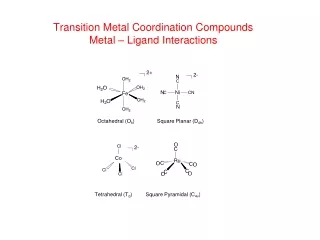
Ligand Field Theory • Text refers to “crystal field theory”. Simpler, but not “valid”. • Ligand theory is better, but full treatment beyond the scope of this course • KEY IDEA: When ligands bind to a metal cation, the ligand orbitals affect the energy of the metal’s d orbitals--some d orbitals’ energies go up, and some go down. We say that the d orbtial sublevel “splits” (into sub sublevels). See diagram, next slide. Ppt07(PS11)
When 6 Ligands Surround a TM cation (octahedral environment), the d-orbital sublevel splits into two “sub sublevels” (my terminology) This is called the d-orbital “splitting pattern” for an octahedral complex. This is the only splitting pattern you need to know for my class(it would change for different geometries and C.N.s). You do not need to know that the top two orbitals are the z2 and x2-y2, etc. Just know that there are “two up” and “three down”. Refer back to Slide 6 to see that this is what we did “before”
Splitting Pattern and D, the splitting energy • The energy difference between the lower “sub sublevel” and the higher one is called the “splitting energy”, with symbol D • D is just short for DE Ppt07(PS11)
D varies in different complexes, but is always small compared to “s to p” or “p to d” gaps! (this is not obvious from text) 4d 4p Free cation 4s D 4d 4p Cation in octahedral complex 4s
Recall (earlier PowerPoint): Absorption at the Molecular Level • Absorption of one photon of visible light corresponds to the excitation of one electron from a lower energy orbital to a higher energy one • The bigger the DE (energy difference or gap) between the orbitals, the greater the Ephoton absorbed • Different gaps yield different colors absorbed, and thus different colors perceived • Changing the DE in a metal complex (or other “dye” molecule) will change the color of the complex (or dye) Ppt07(PS11)
The value of D, although it varies, is “just right” to absorb photons of visible light! (l 400 – 800 nm) This is why transition metal complex are usually colored! The small splitting that develops, results in “gaps” that absorb some visible colors, leaving others to reach our eyes! (More on this later.)
The greater the value of D, the “stronger the (crystal or ligand) field” • Recall that the reason for the splitting of the d orbitals sublevel was the presence of a (crystal or ligand)field. • Think of this “field” as being like an “environment”, imposed by the ligands. • So hopefully it makes sense that the “stronger the field” imposed by the ligands, the greater the D. • “strong field” means a biggerD • “weak field” means a smallerD Ppt07(PS11)
Different ligands tend to impose different “field strengths” • Ligands that tend to make a smaller D are called “weak field” ligands • Ligands that tend to make a larger D are called “strong field” ligands • You do not need to memorize which ligands are of which type. You just need to know the concept (and meaning of “strong / weak field” • Recall the “Fun with colors” expt! Ni2+ with different ligands had different colors! • The type of metal cation also affects D(but again, you just need to know that this is “so”, not “how” or “who does what”) Ppt07(PS11)
Next task… • Now let’s see how we can “populate” the d-orbitals of a TM complex with electrons • This is important because of some of the properties of TM complexes that we’ll discuss later (paramagnetism, color). • This is similar to creating an orbital diagram, except there is a “new” consideration (as you will see) • We’ll start with a review… Ppt07(PS11)
Energy Considerations (reminder)(briefly look back to slide 6 before looking below) Why isn’t the config. for Ru3+this one? [Kr] 5p 4d Ans: Because that configuration would have higher energy than the one on the previous slide. This configuration would describe an “excited state” of Ru3+. That electron in the 5p orbital wouldn’t stay there. It would “fall down” to the 4d. When we write electron configurations or orbital diagrams, we assume ground stateconfigurations. We “want” the lowest overall energy possible. Ppt07(PS11)
Hund’s Rule (revisited) • OK, but what about this one? Why is this is not the correct config? [Kr] 4d Ans: This also has a higher energy! This also represents an “excited state” configuration! Why? Because it takes a bit of energy to put two electrons into the same orbital (electrons repel, right? See next slide for more detail if you like). I call the amount of “energy cost” to put two electrons in the same orbital the pairing energy (P). Ppt07(PS11)
Recap: It “costs” energy to pair up electrons in the same orbital • Electrons repel, so having them in the same orbital makes the energy of the system a bit higher • The amount of energy it “costs” to pair up two electrons is called the “pairing energy” • P = “pairing energy” Ppt07(PS11)
In the past, you could sort of ignore the pairing energy • In the past, once you had put one electron into each sublevel of a “set”, you would then pair up the electrons before populating the next higher sublevel: Next electron would go into 2p, paired, rather than putting it up “higher” into the 3s 3s 2p This is because the price to pair up the electron is much less than the energy needed to “get up to” that 3s orbital (the 2p – 3s “gap”). This was never addressed in 1st semester, but please take a moment to make sure you understand this now. Ppt07(PS11)
Summary of last slide’s “concept” • When “filling up” an orbital diagram, you don’t pair up electrons unless the “price” to go up to the next level is more than the pairing energy Ppt07(PS11)
Preparation for next slide • On the following slide, two complexes are compared. Both involve Co3+, but in one case (with F-’s), the ligands create a “weak field” and in the other (with CN-’s), , they create a “strong field” • In the “weak field” case, the D is so small that it has become smaller than the pairing energy. • As a result, the fourth electron placed into the diagram goes “up” into the higher level rather than pairing up in the lower one! (Click and look below to see the “sequence” of filling) Ppt07(PS11)
Low enough D results in electrons NOT pairing right away P (fixed value) weak-field strong-field D < P D > P Ppt07(PS11)
Explanation of the “high spin” and “low spin” designations on prior slide • As will be discussed on the next couple of slides, an unpaired electron has something called a “spin” and has its own magnetic field. • Thus, the more unpaired electrons, the greater the total spin. • The left complex had four unpaired electrons. The right complex had none (which is fewer than four!). So the left one is called “high spin” and the right one “low spin” • When there is a difference in total spin, the “high spin” one is always the “weak field” one. Ppt07(PS11)
Magnetic Properties are Related to Electron “Spin” • Electrons have a “spin” (up or down) • “Spin” is a Magnetic property • single electron (spin) will attract a magnetic field (“paramagnetic”) • If multiple electrons have the SAME spin in a complex, the complex will be MORE attracted to a magnetic field (more paramagnetic) • Two paired electrons (one up, one down) have no net “spin” (they cancel out) • NOT attracted to a magnetic field Ppt07(PS11)
Spin (continued) • THUS: • If a complex has ALL ITS ELECTRONS PAIRED (“no spin”), then the complex: • Will NOT attract a magnetic field • Is called diamagnetic • If a complex has ONE or MORE UNPAIRED electrons, it: • WILL attract a magnetic field • And the more unpaired electrons (the “higher the [total] spin”), the stronger the force of attraction • Is called paramagnetic Ppt07(PS11)
When is a species colored?(Requirements) • D must have an energy that falls in the range of energies of visible light (photons) • If too large, absorption band is in the UV (or higher) range • If too small, absorption is in the IR (or lower) range (almost never is this small for electronic transitions) • “bottom” energy level must contain at least one electron (or else nothing to “excite”!) • “top” energy level must have at least one “vacancy” (or else nowhere for an electron to “go” to!) • Result? • If no d electrons, no color (Ti4+) • Salts containing Al3+ or Gp I and Gp II cations • If 10 d electrons, no color • Complexes/compounds containing Zn2+ (or Gp III-Gp V metal cations) Ppt07(PS11)
(or electron) Calculating D(per electron) from l of photon absorbed If lmax for some absorption band is 795 nm (red end low energy): Ppt07(PS11)