Download
1 / 22
220 likes | 420 Views
Properties of Micro-Holes for Nozzle by Micro-EDM 微細放電 加工之微噴孔的特性. 碩研機械一甲 M9910114 林泓緯. Abstract

E N D
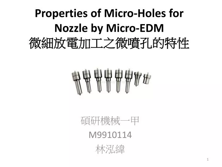
Properties of Micro-Holes for Nozzle by Micro-EDM微細放電加工之微噴孔的特性 碩研機械一甲 M9910114 林泓緯
Abstract • The micro Electrical Discharge Machining (EDM) technique is used for machining hard conductive materialsand achieves holes from 0.05 to 1.8 mm in diameter. The holes are machined with a high repeatability,withoutburrs and material alteration. The technology currently in production in the automotive industry isused to drill diesel and gasoline nozzles coming from the direct injection technology. • One of the most important features, • with respect to diesel nozzle requirements • , is the drilling of positivetapered holes. • This positive taper is mechanically set up, • and offers more possibilities and • better stabilitycompared to • using EDM set up parameters. 由於EDM可加工硬度較高之材料,孔徑能達0.05mm至1.8mm,且具高重複性,無毛邊與材料性質變更,該技術目前在汽車產中運用於柴油與汽油噴嘴技術,對於柴油噴嘴的要求是為錐形孔,此錐度可提供噴嘴更多的可能性與穩定性。
The Electrical Discharge Machining (EDM) technique iswidely used for machining hardened steel. The mostfrequently used application is die-sinking EDM for moldsteel fabrication [1]. Electrical discharges occur betweenan electrode and the conductive material work piece. Theelectrode and the work piece are immersed in a dielectricliquid, which is de-ionized water (< 0.8mSiemens) and theprocess is carried out without mechanical forces. Eachspark melts and vaporizes aterial from both the workpiece and the electrode, which exhibit a wearphenomenon. The EDM ablatedmaterial is flushed awayfrom the spark gap by the dielectric liquid. The holediameters aredetermined by both the electrode size andthe gap extension. A high level of quality in shape andsurface texture (< 0.5 Ra), is obtained without burrs. InEurope, this direction has led to specialized roductionapplications, such as the drilling of nozzles for diesel andgasoline injection. Theintroduction of die-sinking in the90s to process small mechanical parts and micropharmacy applications allowed for a superior level ofprecision.Roughness in the region of 0.1 Ra and spark • gaps of about 5 μm could be obtained. Nowadays, high • quality EDM drilling procedures use rotating electrodes • and axial flushing through hollowed electrodes. At • present, EDM drilling is well established in the field of • manufacturing metal pieces with complicated geometries. • EDM drilling remains the method of choice for diameters • above 50 μm. The geometry of the holes is very important • to the injection nozzle market [2], which has improved • quality and product performances. Tapered holes allow for • better spray efficiency [3], reduction of cavitation • phenomena [4] and self-cleaning of the nozzle holes [5]. • The goal of this article is to show how to control the • conical shape and characteristics of the holes. 由於在(EDM)技術廣泛用於加工高硬材料,其電極與工件都沉浸於介電液中,過程無機械力量,火花融化與蒸發的廢料由電解液帶走,形成一個高層次和質量的表面精度(0.5 RA),在歐洲此技術影響了專業生產化的應用程序,如鑽孔噴射柴油及汽油噴射。 在目前EDM鑽孔是公認製造複雜幾何形狀的金屬工件技術,其直徑超過50μm,幾何形狀的孔洞為噴嘴市場的重要技術,不但提升了其品質與產品性能,圓錐孔有更好的噴霧效率,減少氣泡現象和自行清潔的噴嘴孔,此文章為展示如何控制錐形形狀與特色的孔洞。
傾斜頭部 2 EXPERIMENTAL • Research activities are mainly focused in the field of pulsegeneratortechnology, which is used in order to generate • small spark durations, fine craters and to avoid idle • discharge pulses or short circuits. The rotation of theelectrode, which is maintained by shifting collets andpasses through the guiding collets, is done in order tooptimize quality and drilling speed (seeFigure 1). 可調節環 轉移夾頭:侵蝕軸 引導夾頭 2 EXPERIMENTAL 實驗 研究主要集中在該領域的脈衝發電機技術,用於以產生小火花持續時間,細坑,避免閒置的放電脈衝或短路。旋轉電極是安置於轉移夾頭穿過引導夾頭,是為了其高品質和鑽孔速度(圖1)。
實驗與量測設備規範 淬硬鋼製成的噴嘴(HRC57-63),鉻鎳的鑽孔使用瑞士Posalux公司的FP1的(單軸撓性量產機具)和Posalux的HP4(四軸質量製造機具)進行微細放電加工製造。 電極是淬硬鋼(碳化鎢/鈷,6%鈷)。 測量的直徑,形狀和孔的位置均採用Werth影像檢查IP(image processing)機台。該變化和控制流量由一個 Sonplas機器達壓力138bar(2000psi ) ,根據客戶的要求而定。 • Nozzles made of hardened steel (HRC 57-63), Cr-Ni aredrilled using micro-EDM technologies on Posalux’s FP1 • (One spindle machine for flexible batch production) andPosalux’sHP4 (Four spindles machine for massproduction). The electrode is hardened steel (WC/Co, 6%Co). The measurements of the diameter, shape andposition of the hole are measured using a Werth Video • Check IP machine. The variation and control of the flow isperformed by a Sonplas machine with up to 138 bar (2000psi), depending on customer requirements. 可用量測感測器 圖像處理影像感測器與固定聚焦鏡 變焦感測器 變焦感測器 光纖感測器 Werth機台規格圖表
Posalux-FP1 Sonplas機台規格 Posalux SA機台規格 Posalux-HP4
3 CONTROL OF TAPERED HOLE BY MICRO-EDM The “double clamping” (DC) unit is used to drill holes withcontrol on the geometry. The DC unit is composed ofshifting collets, a tilting head, guiding collets andadjustable rings. The shifting collets move along the Z-axis and provide thein-feed of the electrode during machining. The tilting head allows for control of the run-out of theelectrode, which modifies the diameter of the hole. The guiding collets are set-up to a short and fixed protrusion 雙夾持頭(DC)裝置是用來控制錐形孔之幾何,其組合有:轉移夾頭,傾斜頭部裝置,引導夾頭和調節環,夾頭沿著Z軸進行移動,並提供進料加工之電極。 傾斜頭部(The tilting head)裝置能夠控制進出之電極,修改孔之直徑。 引導夾頭(The guiding collets)是為了短而突出的水平電極而設置的(如圖二所示) 。 調節環(The adjustable rings)可調節電極之斜率修改孔的直徑。
要獲得一個正錐度孔,電極必須以孔入口為對正中心進行加工,負錐度孔則以出口為對正中心進行加工。要獲得一個正錐度孔,電極必須以孔入口為對正中心進行加工,負錐度孔則以出口為對正中心進行加工。 正錐度孔 The adjustable rings set up the slope of the electrode bymechanical adjustment. To obtain a positive tapered hole, the electrode must becentered at the hole entrance on the work piece. Fornegative tapered hole the centering must be done at theexit of the hole, which corresponds to the protrusion andthe wall thickness (see Figure 4). A camera is used to center the electrode. The main advantages of the DC unit are: · The control and the repeatability of the hole diameterby fixing the protrusion and changing the run-out. · The feasibility of tapered hole by fixing a slope on theelectrode and rotating during erosion. 負錐度孔 雙夾頭之優點: 藉由前端凸出部分修正前端與改變其擺動來進行孔控制與其重複性 錐形孔藉由修正電極斜度與旋轉進行腐蝕
The hole is drilled in two steps, the dressing and theerosion. During the dressing step, the polarity used ispositive (electrode positive and work piece negative) andthe idea is to dress the electrode with the aim of obtaininga flat electrode before beginning to erode. Thus the lateralwear of the electrode during erosion will be compensatedfor and each hole machining will begin with the same conditions. Then the polarity is changed (electrodenegative and work piece positive) for the erosion step. Toguarantee good hole exit quality, the electrode penetratesbeyond the end of the hole. 鑽孔分兩步驟:披覆(敷料)與侵蝕鑽孔,披覆電極(電極為正 ,工件為負)目的為取得扁平狀(面)的電極才開始腐蝕,因此橫向磨耗過程中的侵蝕電極將得到補償,對於每個孔開始加工條件相同,然後極性改變(電極為負 ,工件為正)為腐蝕的步驟,目的為保證孔洞的良好品質。 These two processes occur with a rotation between 500-1000 rev/min of the electrode during machining. Rotationof the electrode allows for better flushing of the erodedmaterial and better control of the hole geometry. 此兩個過程轉速為500-1000轉/分,旋轉電極可更佳的沖洗侵蝕材料與控制孔本身的結構。
4 RESULTS AND DISCUSSIONS 4.1 Tapered holes 4.1圓錐孔 Tapered holes can be obtained naturally with EDM drillingparameters by varying the electrode diameters. With theconsistent run-out and with the energy level adapted tothe electrode chosen, the following observations can bemade: 圓錐孔可自然的利用EDM鑽孔改變參數,電極直徑隨著一致的變化並與能階適應電極的選擇。 With small electrode diameters (< 100 mm), the holeobtained has a natural positive cone. 小電極直徑(<100),獲得自然的正錐度孔。 For an electrode with a diameter of 100 mm, acylindrical hole is obtained. 電極直徑為 100,獲得圓柱孔。 With large electrode diameters (> 100 mm), the coneobtained is negative. 大電極直徑(>100),獲得負錐度孔。
As shown in Figure 5, it is mechanically possible to controlthe hole geometry with the adjustable rings by changingthe taper set-up value. A slope is given to the electrodethrough mechanical adjustment. The rotation of theelectrode allows a round hole with the desired taper. 圖五 為可控制孔的幾何形狀與調節環錐度之夾具 其斜度是考慮到電極旋轉加工時所需錐度
負錐度 圓柱孔 正錐度 正錐度 圖六 錐度和正向錐度的可行性 隨著各項目標,取得圓錐形幾何形狀,從而錐形裝置的調節環進行調節 該電極直徑為110mm,管壁為1mm 第一張為負錐度孔 第二張為圓柱形 三和四為正錐度孔 In Figure 6, the cut of various machined holes can be seen, with the goal of obtaining various conicalgeometries, thus changing the taper set-up of theadjustable rings. The electrode diameter is 110 mm andthe thickness of the wall is of 1 mm. The entrance hole isat the top of the image and the exit hole at the bottom. Inthe first cross section, the taper is negative, the secondcylindrical and the two last are positive cones withdifferent conical values. 錐度變化為±30μm
4.2 Small diameter The study of the maximum hole depth for through holeshas been made by varying the electrode diameter. Graph2 shows the erosion time for various electrode diametersas a function of the hole depth. Increasing the electrodediameter allows for larger through hole depths. A changein the graph slopes can be seen for all hole diameters,indicatinga limit of the zone under control. The hole depthcorresponding to the change in graph slope is the holethickness limit where the time and the hole quality isguaranteed. For higher hole depth values, the time oferosion increases and the hole quality is no longer undercontrol in terms of repeatability. For small electrodediameter, the lateral gap is small and the eroded particlesare trapped which makes evacuation difficult. Thisexplains the increase in erosion time and lack of controlover hole quality.The holes diameters are limited based on hole depth, witha ratio of between 1/10 to 1/12 (hole diameter/hole depth).For identical hole depths, the erosion time decreaseswhen the electrode iameterincreases. This is primarilydue to the increase in the supplied energy that could be applied to a larger electrode. 圖二顯示為各時間與電極直徑的比,提高電極允許通過直徑較大的孔深,圖中可看見斜坡與各孔徑,表明限制區是受到控制的,圖中的斜率是孔壁厚與品質的保證,對於小孔徑來說,橫向差距小,使得侵蝕粒子疏散困難,這解釋侵蝕時間的增加和缺乏控制 在有限的孔深基礎上,介於1/10至1/12(孔徑/孔深),相對於相同的孔深,當電極直徑增大時侵蝕時間減少,這主要是增加提供的能量,較適用於較大的電極
4.3 Thickness of the white layer Micro-drilling technologies have the capacity to minimizethe thermal affected zone. White layer thickness has beenstudied with various energies levels corresponding to applications such as diesel nozzles, diesel adapter platesand gasoline nozzles. The material drilled is hardenedsteel which is typically used for diesel nozzles. The drilled plates have a thickness of 0.6 mm. Two cuts wereachieved: · A vertical cut in the axis of the holes. · A horizontal cut, at 120 mm from the top of the surface. The parts were etched in order to investigate the whitelayer. 微鑽孔技術有能力盡量減少熱影響區,白層厚度被與不同能量等級對應噴嘴應用做研究,例如:柴油噴嘴,柴油適配(配置)版(adapter plates) ,汽油噴嘴。柴油噴嘴材料通常使用硬化鋼材(hardened steel)。 鑽孔版的厚度為0.6mm 兩板切銷結果為: 一個垂直的軸切割,一橫向切割再120mm的頂部表面 這些部件被腐蝕,進行白層調查
低能階 低能階(每火花約6 千分之一焦耳)通常被使用於目前柴油噴嘴生產之鑽頭直徑50mm至150mm。白層的研究製作,使用電極直徑70mm 白層厚度沿著洞口變化1和1.5mm 。 高能階 高能階(約10 千分之一焦耳)通常用於鑽頭直徑150mm至300mm,適用於柴油適配(配置)版(adapter plates)。電極直徑為150mm,白層厚度可達3.5mm。 使用較低的能量可降低白層厚度,但加工時間將增加,需大幅度的進一步測試,以了解白層厚度與其影響噴嘴效率。 總之,由於電極使用間無顯著差異,故白層之形成完全取決於能量等級 Low energy Low energy levels (~ 6 mJ per spark) are typically used to drill diameters from 50 mm up to 150 mm, which corresponds to the diesel nozzles currently being produced. The white layer studied here was produced using a 70 mm electrode diameter. The thickness of the white layer along the hole varies between 1 and 1.5 mm. High energy High energy levels (~ 10 mJ per spark) are used to drill diameters from 150 mm to 300 mm and correspond to applications such as diesel adapter plates. The white layer obtained has a thickness up to 3.5 mm and was produced using an electrode diameter of 150 mm. It is possible to reduce the white layer thickness using lower energy, but the machining time will increase drastically and further tests need to be done in order to understand the white layer thickness and its influence interms of nozzle spray efficiency. In conclusion, no differences were observed due to the electrode type. Therefore, the white layer remaining after the micro-EDM process is dependent exclusively on the energy level.
4.4 Roughness 4.4粗糙度 加工後的表面,其特徵分別由四種不同的組成:型態(Form),波紋(waviness),粗糙度(roughness),微粗糙度(micro-roughness) 型態(Form)為工件表面上的表面處理後的長波紋 波紋(waviness)是根據不同水平位置,表面變化較慢的紋理 粗糙度(Roughness)則是根據水平位置,迅速變化的紋理 微粗糙度(micro- Roughness)是優良成分的表面紋理 The topography of a work piece can be characterized by four distinct components: form, waviness, roughness and micro-roughness. Form is a component of surface finish with a long wavelength on the work piece. Waviness is a surface texture component varying slowly,dependingon the horizontal position. Roughness is a of surface texture component varying rapidly, depending on the horizontal position. Micro-roughness is the fine variation component of surface texture.
4.5 Shape measurements The Werth machine is used in order to control the position and the geometry of the hole. Recognition of the hole is made by CCD camera and a fiber probe composed of an optical fiber with a ball at the end. This probe makes possible precise measurements of weak geometries. The detection of very small elements can be obtained with maximum precision and minimum palpation pressure. Theuncertainty of palpation is 0.5 μm and the uncertainty of palpation pressure is 1μN. With the CCD camera, the hole is centered and the probe is positioned in the optical field and inserted into the hole at a specific Z value. At this Z value a palpation is made. There is a limitation on the Z value measurement dependent on the hole depth due to low light emission from the bottom of the hole. The results show an average of variation of ± 2 mm at the hole entrance and of ± 4 mm at the hole exit. But these shape measurements can not be performed in process due to its duration. 4.5外型尺寸 本實驗為了控制位置和孔洞幾何形狀,採用The Werth機台 孔洞是由CCD相機與光纖探頭進行量測,探頭末端由滾珠所組成,因此可精確量測為小的集合形狀,可獲得最大精度與最低接觸壓力 此接觸量測誤差為0.5μm,CCD相機以洞口為中心,並光場內,差入指定的Z值作為量測之依據,在探針觸診量測時,Z值隨著改變。
4.6 Flow measurements The way to control in process the reproducibility of the holes is a flow measurement. The Sonplasmachine performs static flow measurements on nozzles. The high reproducibility of the holes drilled on Posalux machine performs a flow variation in ± 3 % of a nominal value. 4.6流體測量 要控制孔洞的重現性,方法是透過流體的量測 The Sonplas machine進行噴嘴靜態流體量測 Posalux machine進行鑽孔的高重現性流體變化在±3%的公差 5 CONCLUSION At the moment, due to the technological control of the EDM process, it is possible to fully answer the high pressure direct injection needs of the automotive industry. However, current work indicates that there is considerable potential with regards to higher geometrical hole control and reductions in erosion time. The production of tapered holes for diesel nozzles is currently under control and the market of gasoline direct injection is beginning to develop with very similar needs [6]. 5.結論 目前由放電加工可充分滿足高壓直接注入需求的汽車行業,但目前還有許多關於幾何控制(鑽孔外型)與侵蝕時間,生產圓錐柴油噴嘴孔的市場與目前汽車直噴的發展有著非常相似的需求
6 ACKNOWLEGMENTS Authors are grateful to Neode for their scientific results and to Sarix for the micro-EDM technological support. 7 REFERENCES [1] Ho K.H., Newman S.T., 2003, State of the art electrical discharge machining (EDM), International Journal of Machine Tools and Manufacture, vol43,issue 13, 1287-1300 [2] Diver C., Atkinson J., Helml H.J., Li L., 2004, Micro-EDM drilling of tapered holes for industrial applications, Journal of Materials Processing Technology, vol 149, 296-303 [3] Prescher K., Astachow A., Krüger G., Hintze K.,1998, Effect on nozzle-geometry on spray breakup and atomization in Diesel engines experimental investigations using model nozzles and real injections nozzles, Cimac Congress Copenhagen,Band3, 1073-1083 [4] Chaves H., Knapp M., Kubitzek A., ObermeierF.,SchneiderT., 1995, Experimental Study of Cavitation in the Nozzle Hole of Diesel Injectors Using Transparent Nozzles, SAE Transactions, vol 104, n°3, 645-657 [5] Dürnholz M., Wintrich T., Polach W., 2001, Potenzial der Einspritzung zur Reduzierung der Schadstoffemission von Diesel Motoren, Fortschritt Berichte, Reihe 12, Band 455 [6] Ishima T., Sukena R., Liu C., Obokata T., Kawachi K., Kobayashi K., 2001, The Fifth International Symposium on Diagnostics and Modeling of Combustion in International Combustion Engines (COMODIA 2001), 493-498
參考資料:1. 中國百科網-溶蚀钻孔进一步进步激光精度http://www.chinabaike.com/z/jichuang/497192.html2.DirectIndustry- The Virtual Industrialhttp://www.directindustry.com/3.Exhibition Micro Machining MicroforDivisionhttp://www.posalux.net/microfor/f/company/謝謝聆聽
Various measurements have been performed on work pieces machined with different energy levels. Roughness is an indication of the type of machining used. In fact, given the same electrode diameter, the change of energy is visible in the roughness values. For lower energy levels, the roughness is smaller (around 0.3 Ra), than for higher energy levels. This is essentially due to the fact that the energy per pulse is higher and that the material removal rate is a priority. This implies that the roughness depends essentially on the energy used for erosion. Traditional surface finish analysis consists of studying surface texture roughness and waviness. This implies that form and micro-roughness components do not need to be evaluated. A study of roughness can give an indication on the variability of the flow measured. The friction due to the roughness can be one of the major factor for this variability. A study on roughness needs to be undertaken to understand its importance. 加工能量不同,粗糙度是顯示該加工的類型 事實上,由於同樣的電極直徑,粗糙度值隨著能量跟著改變 相對於較低的能量水平,粗糙度較小(約0.3RA),低於較高之能量水平,意味著粗糙度取決於侵蝕時的能量高低 傳統表面光亮度分析包括表面紋理(surface texture)的粗糙度(roughness)與波紋度(waviness)這意味著型態(form) and微粗糙度( micro-roughness)不需要評估 表面粗糙度可指示出的流量測量的變化,由於摩擦是粗糙度的一個主要因素,所必須明白其重要性