Download
1 / 57
570 likes | 589 Views
WinTR-55 Modeling Multiple Sub-area Watersheds. WinTR-55 Development Team. Sub-Area and Reach Concepts. Watershed - system of sub-areas and reaches Sub-areas - watersheds that generate runoff Reaches - represent watershed flow paths (stream channels) or structures. B. A. C. Reach 1c. D.

E N D
WinTR-55Modeling Multiple Sub-area Watersheds WinTR-55 Development Team
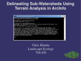
Watershed- system of sub-areas and reaches Sub-areas- watersheds that generate runoff Reaches- represent watershed flow paths (stream channels) or structures B A C Reach 1c D Reach 2e E Sub-area/Reach Concepts TR-55 Tutorial
Sub-area/Reach Concepts • Watershed - system of sub-areas and reaches • Sub-areas- generate runoff • feed into the upstream end of reaches • Reachesor Routing Elements- represent watershed stream flow paths or structures • ChannelRouting elements - Stream Reaches • StructureRouting elements - Reservoir/Structure Reaches • Watershed Outlet- downstream end of the watershed (required for all watersheds) TR-55 Tutorial
Sub-areaA Reach 1a(storage routing) Sub-area B Sub-areaC Reach 2c (Reach Routing) Legend: Storage Area Sub-Area Inflow Points Outlet Schematics TR-55 Tutorial
Data Requirements • Identification Data - User, State, and County • Dimensionless Unit Hydrograph • Storm Data – for specific County/State • Sub-area Data - Name, flows to reach/outlet, area, runoff curve number, & time of concentration • Reach Data -Name, receiving reach/outlet, reach length, Manning’s “n”, friction slope, bottom width, average side slopes TR-55 Tutorial
Adding Sub-areas TR-55 Tutorial
Adding Stream Reaches • WinTR-55 Main Window • Reach Data Window • Reach Flow Path Window TR-55 Tutorial
County Road Upper Main Upper East Middle Main Upper West Lower East Lower Main Lower West Outlet Watershed Schematic MainStem1 WestReach EastReach MainStem2 TR-55 Tutorial
WinTR-55 Main Window TR-55 Tutorial
Adding Stream Reaches • WinTR-55 Main Window • Reach Data Window • Reach Flow Path Window TR-55 Tutorial
Stream Reach Data • Data compiled prior to input: • Reach Name • Name of receiving (or downstream) reach (could be Outlet) • Cross-section data: • Manning’s “n” • Friction slope • Bottom Width • Average side slopes TR-55 Tutorial
Reach Data Window TR-55 Tutorial
Reach Data Window TR-55 Tutorial
Plotted Channel Rating TR-55 Tutorial
Computing Stream Reach Ratings • Manning’s Equation for Channel Flow: Q = discharge (cu ft/s) r = hydraulic radius = A/pw A = cross-sectional flow area (sq ft) pw = wetted perimeter (ft) s = slope of hydraulic grade line (channel slope, ft/ft) n = Manning’s roughness coefficient for open channel flow TR-55 Tutorial
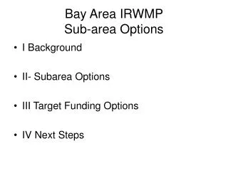
1 D z 1 z BW TW Trapezoidal Cross-Section TR-55 Tutorial
Reach Data Window TR-55 Tutorial
Adding Stream Reaches • WinTR-55 Main Window • Reach Data Window • Reach Flow Path Window TR-55 Tutorial
Reach Flow Path Window TR-55 Tutorial
Number of sub-areas 1 - 10 Number of reaches 0-10 Types of reaches Channel or Structure Channel Reach Routing Procedure Muskingum-Cunge Capabilities & Limitations TR-55 Tutorial
Modeling Watersheds with Structures Sub-area and Reach Concepts
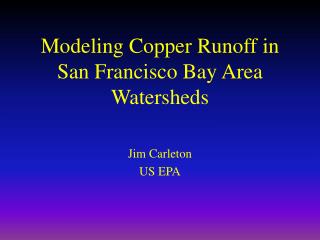
Watershed- system of sub-areas and reaches Sub-areas - watersheds that generate runoff Reaches- represent watershed flow paths (stream channels) or structures N Sub-area / Reach Concepts Sub-area A Stream Reach 2c Stream Reach 1b Outlet Structure Reach Pond Sub-area B Sub-area C TR-55 Tutorial
Sub-area/Reach Concepts • Watershed - system of sub-areas and reaches • Sub-areas- generate runoff • feed into the upstream end of reaches • Reachesor Routing Elements- represent watershed stream flow paths or structures • ChannelRouting elements - Stream Reaches • StructureRouting elements - Reservoir/Structure Reaches • Watershed Outlet- downstream end of the watershed (required for all watersheds) TR-55 Tutorial
Sub-area A Reach 1a(storage routing) Sub-area B Sub-areaC Reach 2c (Reach Routing) Legend: Storage Area Sub-Area Inflow Points Outlet Schematics TR-55 Tutorial
Adding Structure Reaches • WinTR-55 Main Window • Reach Data Window • Structure Data Window • Reach Flow Path Window TR-55 Tutorial
WinTR-55 Main Window TR-55 Tutorial
Adding Structure Reaches • WinTR-55 Main Window • Reach Data Window • Structure Data Window • Reach Flow Path Window TR-55 Tutorial
Reach Data Window TR-55 Tutorial
Reach and Structure could be the same Name. Naming Reaches TR-55 Tutorial
Adding Structure Reaches • WinTR-55 Main Window • Reach Data Window • Structure Data Window • Reach Flow Path Window TR-55 Tutorial
Structure Data Window TR-55 Tutorial
Spillway Types Pipe Weir
Pipe Spillway TR-55 Tutorial
Straight Pipe TR-55 Tutorial
Drop Inlet Pipe TR-55 Tutorial
Pipe Flow Equations where: g = gravity cd =0.6 Height, feet Headpipe,feet Stage, feet Dpipe ,inches Apipe,square feet Flowpipe,cfs TR-55 Tutorial
Pipe Flow Assumptions • Short-tube approximation – assumes orifice flow through the pipe at all stages • Reasonable for drop inlet configuration • May be unreasonable for large straight pipes • If not appropriate, use other routing models • SITES • WinTR-20 TR-55 Tutorial
Pipe Flow Assumptions TR-55 Tutorial
Spillway Types Pipe Weir
Weir Spillway TR-55 Tutorial
Weir Configuration TR-55 Tutorial
Weir Flow Equations where: Lweir = weir length, feet Stage, feet Flowweir, cfs TR-55 Tutorial
Weir Flow Assumptions • Entry of a zero weir length indicates a 90° v-notch weir • Other entry for weir length indicates a rectangular – having vertical sides - broad-crested weir TR-55 Tutorial
Plotting Structure Ratings TR-55 Tutorial
Storage-Indication Routing Method • Estimates how the hydrograph changes as it flows through a structure • DStorage = (inflow - outflow) * Dt TR-55 Tutorial