Download
1 / 14
140 likes | 267 Views
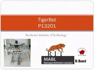
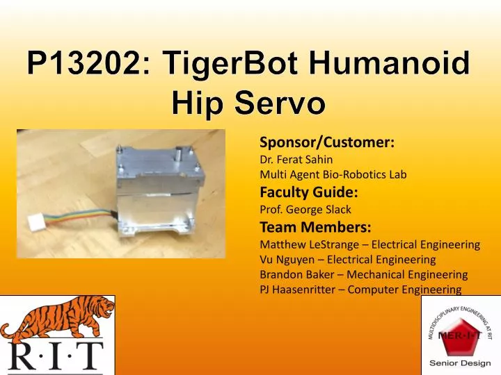
P13202: TigerBot Humanoid Hip Servo. Sponsor/Customer: Dr. Ferat Sahin Multi Agent Bio-Robotics Lab Faculty Guide: Prof. George Slack Team Members: Matthew LeStrange – Electrical Engineering Vu Nguyen – Electrical Engineering Brandon Baker – Mechanical Engineering

E N D
P13202: TigerBot Humanoid Hip Servo Sponsor/Customer: Dr. FeratSahin Multi Agent Bio-Robotics Lab Faculty Guide: Prof. George Slack Team Members: Matthew LeStrange – Electrical Engineering Vu Nguyen – Electrical Engineering Brandon Baker – Mechanical Engineering PJ Haasenritter – Computer Engineering
Problem: • Several Senior Design groups have worked on building a “Tigerbot”, a 2-3 ft. tall walking Humanoid Robot. • A continuing problem with off-the-shelf servo motors within their budget could not provide the necessary torque for the loads on the hip joints. • The goal of this project is to create a low-cost servo that provides the necessary torque and speed for a walking robot. • Additional goals are to have modular design a smart digital interface to communicate with the robot
High Level Customer Needs • Design a high torque/high speed servo motor suitable for a walking robot • Make the enclosure design modular to allow servo to be used in different robotic joints • Modular gear box design for variable speed vs. torque, optional dual output shaft • Design a communication interface to between servo motor and the robot controller send feedback and receive commands
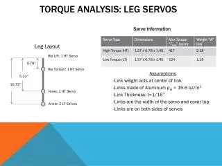
High Level Specification Mechanical • Provide sufficient torque for the hip joint (approx ~700 oz-in) • Torque specs based on size/weight of the servo • (100-200oz-in/in^3 and 100-200 oz-in/oz) • 3 Gear Ratio Configurations Electrical/Computer • Control Position using PWM or CAN bus interface • Provide Feedback for position, current and Read control loop variables via CAN bus • Operate on a 6-8V range • Control Motor (CW, CCW, active brake and coast modes)
Concept Selection Summary • Mechanical Enclosure, Aluminum vs. Plastic • Aluminum is easier to machine for producing a prototype • Good for Thermal Dissipation • Low Cost • Encoder Selection (Potentiometer, Optical, Magnetic) • Most servos use potentiometer • Simple analog interface to microcontroller • Relatively easy to create dual output shaft • H-Bridge Selection • Use discrete IC, smaller space, easy to implement all functions (CW,CCW, Brake, Coast) • Built in current sensing, short circuit and over temperature protection
Design Highlights (Mechanical) • Aluminum enclosure • Multiple mounting options • Heat dissipation • Easily change between ratios with no changes to the enclosure • Modular gearboxes • 3 Gear Ratios for variable torque output • 211:1, 264:1, 330:1 • Optional Dual Sided Output Shaft CAD Model Cutaway View CAD Model Mounting Holes
Design Highlights (Electrical/Computer) • 4.5V to 9V Battery Supply (Motor Limiting Factor) • Small PCB Design (1.61 in2) • Robust H-Bridge • Automatic Temperature and Short Circuit shutoff • Current Monitoring • Active Braking 1.15” 1.4” PCB Top View PCB Bottom View Finished PCB
Design Highlights (Electrical/Computer) • Multiple Servo Position control interfaces • PWM – Standard Servo Interface • CAN – Smart Interface • 12-bit position and current measurement feedback system • Robust, fault tolerant control system • PID Control System • Field programmable PID Gains values • CAN Bus Interface • Current, position, and status feedback • Control up to 31 servos on a single 2-wire bus • Servo configuration read/write: PID gains, maximum power, address, servo mode
Final System Results • Operates from 4.5 to 9V • PWM or CAN position control • Working CAN feedback/communication system • Initial Testing: 596 oz-in stall Torque • Gears for different gear ratios (211:1, 264:1, 330:1)
Project Budget Note: Does not include Tax/Shipping charges for most orders
System Cost Current Design Material Cost • Current Labor Hours • PCB assembly: 1-2 hrs • Gears/Shaft: 3-5 hrs • Enclosure: 10-15 hrs • Assemble Servo: 1 hr • Program/Tune/Test Servo: 1 hr • Total: 16 to 23 hours
Future Improvements • Increase motor size/torque output for 5 ft. tall robot • Minimal changes to electronics needed to use 12V supply • Continuous 360ᵒ rotation, use 2nd output from Potentiometer • Additional Feedback (torque, velocity, temperature, stall warning) • Add attachments to attach to standard servo horns
Design For Manufacture Improvements • Simplify Enclosure Design • Injection Molded Plastic • Extruded Aluminum ($4-15/each) • Cut all gears from stock • $7-16/gear vs. $1.60-2.80/gear & increased machine time • Buy compound gears Potential Future Cost after Redesign