Download
1 / 35
360 likes | 479 Views
Case Study Computer Controlled Radiation Monitoring System. Prepared by: A.siminfar, A.bahrami Presented By : Abbas Bahrami Health physics officer & Network Administrator bahrami@nrcam.org. Nuclear Research Center for Agriculture & Medicine Atomic Energy Organization of IRAN. ALARA.

E N D
Case StudyComputer ControlledRadiation Monitoring System Prepared by: A.siminfar, A.bahrami Presented By : Abbas Bahrami Health physics officer & Network Administrator bahrami@nrcam.org Nuclear Research Center for Agriculture & Medicine Atomic Energy Organization of IRAN
ALARA • Radiation protection is an important rule in practices that involve radioactive sources. • For reducing the absorbed dose of personnel, the working areas must be under control. • For this, the health physics officer must be able to monitoring all hot areas.
Requirements • Single area radiation Monitor (stand alone) • Area radiation monitoring System
Single Area Radiation Monitor • Measures the environment dose rate around the detector • Displays the measured value on a display board • More sensitive than other dose monitors (e.g. Personal dosimeters
Area Radiation Monitoring System • Consists of several single area radiation monitors, that is controlled through a central unit • Communication between monitors and central unit is carried out by a network • Measured values on monitors are displayed in central unit (on line) • Data is stored in central unit for further uses
Computer Controlled Area Monitoring System Consist of: • 1- Area radiation monitors (called as terminals) • 2- Central control unit (PC) • 3- Network RS485 (Design a network and define a protocol)
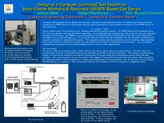
Area radiation monitor (Terminal) (Implemented system) A terminal mounted in waste room
Two Area Monitors installed in the Hot Cell Laboratory of Cyclotron
1- Normal State LED2- Warning LED3- Alarm LED4- Audio Alarm ON LED5- Audio Alarm OFF LED6- Set Alarm ON/OFF7- Pulse LED8- Setting Display Un 9- Display Count/Sec LED10- Display Dose Rate LED11- Display 7_SEGs12- CAT5 Connectors13- CAT5 Connectors14- Fuse15 – Detector Probe Top View Front View
Connection of Area Radiation Monitor to BUS-RS485 • Send line ADM485 is enabled by the Microcontroller for releasing the BUS after sending data • Using ADM485, Microcontroller’s serial data in TTL format is converted to RS 485 format
Terminals connected to the central computer via an interface module • Communication between the terminals and interface is carried out by two transmission lines for send & receive, using RS485 standard
Has been Designed for 8051ED2 Microcontroller by assembly language • Has been designed for : • Count and Process the output pulses of the detector • Calculate the dose rate regarding to pulse rate • Display the dose and count rates • Alarm in high dose • Communication with the Interface • communication with user by some micro-switches and display board Software of Area Monitors (Terminals)
Central Control Unit • Designed By VC++, so it is object oriented • Can be run with Windows • is user friendly • Has following duties: • Communicate with terminals via interface • Show the dose rate of terminals On line • Save the data in DB ( *.mdb Access format) • Show off line data in daily, monthly and yearly graphs • Make Reports • Adjust Alarm level of terminals
Networking of The System Using RS485 Standard
RS485 Standard • Terminals is connected to the central computer via an interface module • The communication between the terminals and interface is carried out by two transmission lines for send & receive, using RS485 standard • Interface module controls the network and acts as a BUS master
RS485 Standard Advantages • Simple and low cost hardware (no Hub, switch and Ethernet card are needed ) • Distance between terminal and central control can be increased (up to 5 Km) • Possibility of saving data in the interface when the computer is off
RS485 Standard Disadvantages • Need to design and apply a suitable protocol • A hanged terminal may occupy the BUS (in the end of communication between a terminal and Interface, terminal must release the BUS) • A central computer is required for connecting to the terminals (terminals can not be connected to Ethernet directly) • In Existence of LAN, another cabling is need for this system • An interface module for connecting the BUS to computer is required
Development for future • IP-Based (in progress) • Web Based Monitoring (Connecting Monitors directly to Internet)
IP Based Area Radiation Monitoring System • Using serial to TCP/IP converter (Network Enabler for Serial Device), monitors are connected to LAN and controlled by a central computer • Without considering converter, each terminal is the same as the last one. • An IP address is assigned to each terminal’s converter • Data is sent in the format of TCP/IP from central computer, the converter extracts the pure data and pass it to the terminal’s microcontroller
Ethernet IP Based Area Radiation Monitoring System
IP Based System Hardware modification Hardware modification in the IP-Based System regarding to RS485: • Add a Network enabler device (Serial To TCP/IP Converter) in each terminal instead of TTL to RS485 converter • No need to an Interface module • Use HUB/switches in network • Ethernet card in control computer
IP Based System Software modification Software modification in the IP-Based System regarding to RS485: • In the Terminal software: • Network Enabler (Converter) in each terminal causes: • A terminal receive only its own data • A terminal send data without any request - data collision do not happen • In the Central Computer Software: Connecting to the Network Enabler Devices instead of interface that was carried out by serial port in the last one
IP Based System Advantages • In Existence of LAN, no extra cabling is needed • TCP/IP is the transmission protocol, no new protocol in needed • High reliability of the network
IP Based System Disadvantages • HUBs/Switches is needed for networking • Network Enablers for Serial Device is Needed • To connect a computer in the LAN directly to a terminal, a software must be installed in the computer • Terminals can not be directly connected to internet
Web Based Monitoring System • Web pages must be designed in terminals • Terminals must support TCP/IP protocol
Web Based System Advantages • From all over the world each terminal can be accessed via internet • Central computer can be anywhere • Protocol and network hardware are standard