Download
1 / 24
240 likes | 407 Views
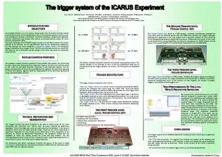
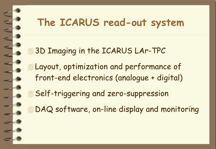
The ICARUS read-out system. 3D Imaging in the ICARUS LAr-TPC Layout, optimization and performance of front-end electronics (analogue + digital) Self-triggering and zero-suppression DAQ software, on-line display and monitoring. The ionization chamber (LAr).

E N D
The ICARUS read-out system • 3D Imaging in the ICARUS LAr-TPC • Layout, optimization and performance of front-end electronics (analogue + digital) • Self-triggering and zero-suppression • DAQ software, on-line display and monitoring
The ionization chamber (LAr) dW = E e (v+ + v-) dt = V0 i0 dt i0 = e (v+ + v-) / d ~ e v– / d (v– >> v+ ) Q(x) = ∫i0 dt = e (d - x) / d • i0 starts as soon as the event occurs • space resolution given by the size of the capacitor • a charge outside the capacitor is not detected
The 3D imaging in Liquid Argon • Yield ~ 6000 electrons / mm • Grid transparency: • E1/Edrift = E2/E1 > (1+r)/(1-r) r = 2pr/p (r=wire radius) • Wire-to-wire shielding: s = 1+log(r) p/(2pd) Edrift u-t view E1 v-t view Edrift = 500 V/cm p = 3mm d = 3mm r = 0.1mm In the ICARUS LAr TPC E2 w-t view E1/Edrift = E2/E1 > 1.4 s > 92%
The induction signals • Electron drift velocity ~ 1.5mm/ms • Typical grid transit time ~ 2-3 ms Induced currentInduced charge T=0 u-t v-t w-t Drift timeDrift time
The ICARUS read-out principle Time Edrift Drift direction Hit finder Mux Memory 8:1 FADC • Continously sensitive • Self-triggering 400ns n x 4kB multi-event circular buffer Low-noise amplifiers To storage Daedalus Front-end
Layout of front-end electronics H.V. (<±500 V) UHV Feed-through (18x32ch.) VME board (18/crate) Liquid argon Gas Sense wires (4-9m, 20pF/m) 4 Multiplexers (400ns x 8ch.) Twisted pair cables (4m, 50pF/m) 10bit FADC 400ns sampling Front-end amplifiers (32/board) Decoupling Boards (32 ch.) ICARUS T300: ~ 27000 channels — 860 boards — 48 crates
The ICARUS T600 read-out chain CAEN-V789 board: 2 Daedalus VLSI * 16 input channels (local self-trigger & zero suppression) + memory buffers + data out on VME bus Signal UHV feed-through: 576 channels (18 connectors x 32) + HV wire biasing Decoupling board: HV distribution and signal input CAEN-V791 board: 32 pre-amplifiers + 4 multiplexers (8:1) + 4 FADC’s (10 bits - 20 MHz)
The analogue board CAEN-V791 FADC’s Multiplexers Digital link Preamplifiers Output of analogue sum Shielding of front-end
Input signals & pre-amp feedback RC • Ext. & Int. planes: • Approx. unipolar input signal • Width ≥ 3 µs • Short RC (“quasi-current” mode) to minimized pile-up • Mid. Plane: • Bipolar signal • Long RC (“quasi-charge” mode) to get triangular signals RC = 3ms RC = 30ms RC = 3ms Expected signal: ~ 15000 electrons (3mm m.i.p.) Equiv. Noise charge: (350 + 2.5 x Cin) electrons = 1200 el.
Optimization of the Analogue boards • Goals (V791C & V791 Q): • Signal P.H. ~ 12 ADC for 3 mm m.ip. • Noise r.m.s ~ 1 ADC • FWHM ~ 5 µs • Action on: • feedback RC • Gain and bandwidth of “baseline restorer” • Results: Overall decay time constants: ~3µs (V791C) , ~30µs (V791Q)
Performance of the V791 boards V791C V791Q 128 wires/view 1024 samples 400 ns/sample • Events (with PMT global trigger) Collection Mid. Induction 1st Induction 1st Induction
Performance of the V791C boards • Single wire waveforms (horiz. axis unit = 400 ns) • RMS noise on T600 = 1.7 ADC counts (due to difficult environment in Pavia) Collection m.i.p. ≈ 12 ADC counts (3 mm) FWHM ≈ 5 µs Test pulse (6 mm m.i.p) 24 ADC counts FWHM ≈ 5 µs Noise RMS ≈ 1.1 ADC counts 1st Induction Coherent noise due to layout not negligible!
Performance of the V791Q boards • Single wire waveforms (horiz. axis unit = 400 ns) • Pulse height & shape from mid. plane wires very similar to those from collection plane wires. • High frequency S/N also comparable. • Low frequency minimized by shaper. Mid. Induction Test pulse (6 mm m.i.p.) 24 ADC counts RC ≈ 30 µs m.i.p. ≈ 10 ADC counts (3 mm) FWHM ≈ 5 µs Noise RMS (h.f.) ≈ 0.8 ADC counts h.f. noise on T600 = 1.5 ADC counts Low frequency noise visible but not dangerous!
Events from the T600 semi-module Collection view Drift time (1.5m) Wire numbering (4.5m) Induction2 view Drift time (1.5m) Wire numbering (4.5m)
Event reconstruction 1 2 • Signal fit: • B = baseline • A = amplitude • t1 = risetime • t2 = falltime • x0 = peak position Landau distributions from x-ing muons A B Tempo (campioni) (1 campione =400 ns) x0 Charge(fC) • Landau parameters (dE/dx, x) in agreement with expectation after: • Test pulse energy calibration • Free electron lifetime correction
The digital board CAEN-V789 Daedalus Circular memory buffer Trigger I/O VME buffer Digital link Trigger and control logic
V791 V789 BOARD BOARD EVENT FIFO EXT. TRIGGERS DAEDALUS LINK CKSYNC CHIPS 2 • 16 ch MUX 8 ANALOG 8:1 CHANNELS CLK 20 MHz DAEDALUS: on-line zero suppressor and local trigger enabler Raw data (ext. trigger) ADC RAM VME INTERFACE Reduced data 32Current/Charge Preamplifiers Daedalus feature: Varying rise-time front-edge finder
Zero-Suppression Algorithm Hitfinder + TileBuilding Daedalus: detects signal Rising-Edge, Falling-Edge, Width… and generates a hitfound signal TriggerLogic: handles a 16 channels group and builds a data tile around the hit Present Performance on T300 RawData: Efficiency= 97% Collection 90% Induction 1 & 2 False Detections= 20% Studies underway for improvement of algorithm (promising…)
Event builder operating modes PMT + Full DriftImaging • External trigger: • Limited in bandwidth (≈1 Hz max rate for 1.5 ms drift). Maximum of two events pile-up before deadtime. • External Enable: • Bandwidth allows up to 1k event “tiles” (25 µs • 16 wires) per second per readout crate. Daedalus thresholds can be more tolerant without over-flooding readout. • Internal FIFO’s can accept up to 128 fragments. • Open Shutter: • Same bandwidth as above. Useful to collect low energy events. • Drawback is that correlated noise bursts even at low repetition rate (few per second) would easily saturate the DAQ channel. Analog OR PMT + Daedalus hit finding Analog OR Daedalus hit finding
18 17 16 7 6 DAQ Read-out Rack Abs Clock & Trigger distribution 20MHz 1 Flanges 2 Cables & Conn. 3 Screening Boxes 4 Decoupl. Boards 5 An. Backplanes 6 An. Crates 7 An. Power Supply 8 Slow Control Mod. 9 Charge An. Boards 10 Current An. Boards 11 Dig. Link Cables 12 Dig. Boards 13 Abs. Clock Trig. Mod. 14 Cpu 15 Dig. Backplane 16 Dig. Crate + P.S. 17 P.S. Fan Temp. Controller 18 Rack 17 18 mv2100 14 13 12 v789 16 15 v816 v873 11 7 v793 v764 4 v791Q v791C 10 2 5 8 9 6 3 1 40MHz HV Wires HV distribution 96 (+4 spares) units on the t600 Air tight structure (to reduce post installation servicing). Fan controlled air flow through the alu heat exchanger moderates internal temperature. A custom unit allows remote probing and control of rack status via an I2C interface.
RC 1 RC 2 RC 23 RC 24 T600@PV DAQ layout Full Imaging Mode : 2 * ~114 MB/ev ~.1 Hz Readout rack interconnection is based on an fast ethernet/giga ethernet switched network. Event fragment merging load can be shared among a set of receivers. One of the receivers also handles synchronization with trigger system. An I2C bus is used for rack remote control. Daedalus Zero Skipping : estimated 2 * ~.5-10 MB/ev 1-100 Hz Open Shutter : max 2.5-4MB/s crate max tile rate ~ 1000 Hz/crate Mvme 2100/vxWorks-linux RC 1 RC 2 RC 23 RC 24 I2C copper FE copper 2-4 MB/s FE/GE Cisco 3524XL Detector Top 10-40 MB/s GE fiber GE/GE Cisco 3508XL Linux Boxes MP 2PCI 700 MHz/512MB/92GB NT/Linux box icab3 B icab5 F E T Trig Builder/Filter DAQ Run Control & Monitor Slow Controls Control Room icab1 icab6 15MB/s LAN icab2 DLT
T600 Builder Overview All communication channles are over tcp/ip sockets. Data are pushed - flow control relies on protocol features ’EVM determines data destination according to periodic status messages sent from writers Synchronization uses absolute time tagging Handles communications with run control to start, stop, housekeep and configure Cpu Software Task Manager Builder Task DATAHead Samples STATStatus Time ERROMessage CONFconf_status Writer Task(s) Local Buffering Controls readout hardware Mem Management Task icab Deals with memory allocation and stats Accept connections. Spawns data collection threads Deals with EVM INITPARAM DEDPPARAM TRGPPARAM EVEN PARAM STRT STOP STAT ERRO Task Manager STAT ERRO Writer pthread(s) Broadcasts configurations Spawns control threads Handles sync Collect data fragments, strip sync messages, Merge data on a file Task Manager Control pthread(s) File System WriterSoftware mpicasr Conf Database WINIPARAM WRIT PARAM EVEN PARAM STRT STOP Trig Control configuration Controls DAQ busy to storage mpicaevm EVM sync
Lossless Compression Scheme Ch 0 Ch 1 Ch 2 Ch 3 … Ch 15 Sample n 32 bytes 434 320 360 412 392 … 16 bits Ch 0 Ch 1 Ch 2 Ch 3 … Ch 15 Achieved compression ratio on t600 data files ~ 3.9 Sample n+1 425 324 358 411 402 … 16 bits Ch 0 Ch 1 Ch 2 Ch 3 … Ch 15 Difference n -9 4 -2 -1 +10 … 16 bits … 2nd clamped diff Ch 0,1,2,3 Ch 12,13,14,15 … 1st clamped diff Encoded Data Sn+1 - Sn +8 if -8< diffn<8 0 else Actual value (16 bits) follows for every clamped difference 12 bytes 12 6 7 0 0 +10 -9 16 bits 16 bits 4* 4 bits hex C670 Each sample is coded on 4 bits as the difference between itself and the previous sample (throwing the 6 bits carrying daedalus output ). Should the difference be outside 4-bit boundaries (< 1% of samples), a flag is raised and the full 16 bits value is then used.