Download
1 / 54
580 likes | 799 Views
Joint Tanker Project Development of Common Structural Rules for Oil Tankers. Joint Tanker Project Overview Technical aspects of the JTP Rules Relationship with IACS (JBP) The Future. Aim.

E N D
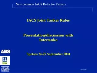
Joint Tanker Project Development ofCommon Structural Rules for Oil Tankers
Joint Tanker Project Overview Technical aspects of the JTP Rules Relationship with IACS (JBP) The Future
Aim To develop a set of unified Rules and Procedures for the determination of the structural requirements for oil tankers
Objective • To eliminate competition between class societies with regard to structural requirements and standards • To employ the combined experience of all three societies to develop a single agreed standard, or set of Rules. • To ensure that a tanker meeting this new standard will be recognised by industry as being at least as safe and robust as would have been required by any of the existing Rules • To embrace the intentions of the anticipated IMO requirements for goal based new construction standards.
Organisation • The project is being led by a Steering Group, reporting to the CEOs of each society. • A team drawn from ABS, DNV and LR manages the technical work packages, using technical experts drawn equally from the three societies. • An External Review Group of senior, experienced technical experts is providing an independent industry input throughout the project. • The Technical Committees of ABS, DNV and LR will be given the opportunity to comment on the Rule proposals.
Deliverables from the project • A new complete Rule set covering the structural requirements for oil tankers for new construction and for those ships subsequently in service. • Supporting guidance to amplify the Rules, including the procedures for carrying out direct calculations and for fatigue life assessment. • A background document explaining the implicit safety levels, design principles and assumptions on which the Rules are based
Scope • The Rules will cover the entire hull structure in a consistent and logical manner, including fore and aft ends. • The Rules will be limited to oil tankers, for crude and products, of length greater than or equal to 150m. • The Rules will cover the hull envelope, transverse and longitudinal bulkheads, main supporting members and local structure. • Simplified approaches for determination of fatigue life and sloshing loads will be included.
Schedule • The draft set of Rules will be available for comment by the Technical Committees of ABS, DNV and LR by end May 2004. • The draft set of Rules will also be available to all IACS members at the same time • Final Rule version approved by ABS, DNV and LR will be published 1 January 2005 and become mandatory on 1 July 2005 • Withdrawal of equivalent existing Rules by ABS, DNV and LR with effect from 1 July 2005
Approach • The new Rules have been developed under a coherent development framework • The new Rules include some new approaches, where there is sufficient confidence and justification for their adoption. • The best and most transparent methods are selected for the new Rules. • The new Rules will be subjected to a major programme of testing and calibration to ensure that the Rules are internally consistent and reflect service experience.
Fundamental principles of the Standard • To ensure that the overall safety of the hull structure is equivalent to or better than that currently achieved in relation to life, environment and property. • To ensure sufficient durability throughout the operational life in terms of corrosion margin and fatigue strength. • To define the minimum state of the structure at which steel renewal is required in order to continue safe operation.
Reliability Durability (fatigue + corrosion) JTP safety level Current safety level Time Objective of RulesFramework for the JTP Rule Development
Design Basis • Design Life – 25 years • External Environment • North Atlantic wave environment • Air temperature : -15 degree C • Sea temperature: 0 degree C • Internal Environment • Specific gravity cargo: Min 1025 kg/m3 (900 for fatigue) • Specific gravity ballast: 1025 kg/m3 • Max cargo temperature: 80 degree C • Min cargo temperature: 0 degree C • Corrosion margins based on 25 years design life
Principal new elements • Net scantling presentation is used throughout the rules • Inclusion of new procedures for the assessment of buckling and ultimate limit state of the hull girder • Inclusion of a new method of describing dynamic loading • Development of a Rule format that provides transparency and ease of use
Principles for Prescriptive Rules • Similar to existing Rules but based on first principles with respect to loads • Loads based on the North Atlantic sea area with 10-8 probability level of occurrence • Presented in a working stress format • Based on net thickness philosophy
Software • The new set of Rules must be supported by software tools. • At the time of the launch of the common Rules for oil tankers suitable rule check software will be available to designers. • ABS, DNV and LR will incorporate the requirements of the new Rules into their existing software solutions.
Benefits to industry • The outcome of this project will be a single, clearly recognised standard that has been developed, with active input from industry, using the combined research and experience of ABS, DNV and LR. • The costs of dealing with a number of similar but different Rules sets will be eliminated. • The efforts of ABS, DNV and LR will be focussed on establishing and maintaining a single Rule set.
Joint Tanker ProjectCommon Scantlings Oil tanker structural requirements will not be a competitive issue for ABS, DNV and LR
Joint Tanker Project Overview Technical aspects of the JTP Rules Relationship with IACS The Future
Joint Tanker Project Net thickness approach Ultimate Limit State Buckling Loads FEM Fatigue Prescriptive Rules
Net thickness approach and wastage allowance • The Rules are presented on the basis of determination of the net scantlings required for adequate strength, with a design corrosion margin. • This approach will result in a unified methodology for the determination of renewal scantlings, which will provide a more transparent estimate of the corrosion margin available before renewal. • To have a direct link between minimum thickness accepted during vessel operations and the thickness used for strength calculations at newbuild. • Strength calculations during newbuilding are based on the net thicknesses of plating and structural members. • Newbuilding gross thickness requirement is calculated by the addition of expected wastage during the vessel design life to the required net thicknesses.
Owner’s Extra Net Thickness tw tgross required tcorr tcorr 2.5 tSiO renewal tnet required Corrosion allowances based on published IACS data, in mm based on 25 year design life
Net Thickness Definitions Wastage between inspection, local structure The assumed wastage during inspection intervals is referred to as t corr_2.5 and links the corrosion addition and the allowable wastage thus: t corr = t waste + t corr_2.5 The 2.5 suffix indicates inspection periods of 2.5 years as in existing survey schemes. The JTP Rules take t corr_2.5 as 0.5 mm
Corrosion Wastage Allowance (mm) Long.bhd 2.5 Deck trans Web 2.5 Face plate 3.0 Deck 3.5 Internals in upper portion of WBT 3.0 Long stiff. 2.5 Sheerstrake 3.5 To 1.5 m Below Deck Long bhd stiff 2 Stringer 2.5 Inner skin 2.5 Side shell 2 Face plate cross-tie 3 Web cross-tie 2 Long stiff. 2.5 Web plate 2.5 Long.bhd 2 Face plate 3 Hopper 2.5 Long. Girders 2.5 Long stiff. 2.5 Bottom 3.5 Keel 4.5 inner.bottom 3.5
Net Thickness Philosophy for Simplified Fatigue Calculation Simplified fatigue assessment Local stresses calculated with average dimunition of the stiffener web, plate flange, and face plate. t fatigue = t gr offered – 0.5 * t corr t fatigue = t net offered + 0.5 * t corr
Net Thickness Philosophy for FE Fatigue Calculation • Corrosion deduction used for cargo hold FE model is based on average corrosion which is less than full corrosion designated t corr t corr_FE cargo = 0.5 * t corr • The cargo hold FE model is therefore built up based upon t = t gr offered – 0.5 * t corr • For the modelling of structural elements that act as single components (e.g. a cross tie) the full deduction t corr is to be used since the “large area reduction” does not apply. • For local model areas with fine mesh the full deduction t corr is to be applied.
Net Thickness Philosophy for Buckling Calculation • The buckling capacity is based upon t net offered = t gr offered – t corr This ensures consistency with the approach to buckling due to pure longitudinal stresses.
Hull girder - ultimate limit state • Prescriptive requirements for single failure of local elements based on IACS Unified Requirements • Introduction of a simplified ULS assessment procedure based on method under consideration within IACS • Consideration will be given to a more comprehensive approach later
Buckling • New buckling procedure • Strength assessment of stiffened thin plate elements in ship structures
Loads • Clear description of load definition and load application • Load combination factors are used • Rule design wave loads based on current IACS practices • Load formulations have been validated by direct calculations • Sloshing, slamming and bow impact loads use available current methods
Basic Concept of JTP load model • Green sea loads • Sloshing pressures • Bottom slamming pressures • Bow impact pressures
Strength Assessment (ULS/SLS) Fatigue Assessment (FLS) Most severe load expected Expected load history Equivalent design wave approach Selected load cases for maximised responses Rule load at 10-8 *Load combination factors Weibul distribution for total stress range Basic concept of JTP dynamic load model Long-term distribution approach Rule load at 10-4 Stress combination factors
FE Analysis Procedure To verify the ship structure meets the required standard: • Strength assessment Coarse mesh FE cargo tank analysis Fine mesh FE local structure analysis • Fatigue assessment Very fine mesh FE fatigueanalysis
FE Analysis Procedure Strength assessment Cargo tank FE model
Principles for Fatigue Procedure • Simplified fatigue procedure for end-connection of longitudinals • Simplified fatigue procedure based on FEM for selected critical details; e.g. hopper knuckle • Principles • Minimum design life 25 years in North Atlantic • Classic Palmgren-Miner cumulative fatigue damage methodology • Long-term stress distribution
Fatigue Assessment Procedure • Representation of long term distribution of stress ranges • Design S-N curves
FE Analysis - Fatigue assessment Dynamic fatigue loads • Tuned on 10-4 probability level, North Atlantic • Load combination factors - relative phase relationship between loads accounted for • Cargo density, SG > 0,9 Fatigue loading conditions • Full load and ballast used for dynamic loads • Static loads included for mean stress effect
FE Analysis - Fatigue assessment • Hot spot stress calculated using very fine mesh FE analysis (mesh size t x t) • Model based on average (over life) corroded thickness, tgross – 0,5 tcorr • All potential fatigue sites to be investigated
Rules Design Principles Consequence Document Background Document Appendices Rules Document Overview • The JTP Rules package:
The Rules Structure Underpinning Principles: • Transparent and modular • Easy to use and identify requirements • Logical flow core structure from design principles to design verification • Self-containment where possible • Inclusion of direct calculation procedures • Comprehensive Rules but with detailed procedures in appendices • Rules will be supported by a Background Document
The Rules Structure Rules Background Document: • Contains more information or background • Explains safety objectives • Explains design principles • Rules sub-section by sub-section approach • Specific version for external use • Useful for training new users of the Rules
The Rules Structure Consequence Document: • Incorporates impact on scantling requirements applying the JTP Rules to current designs • Covers all technical aspects but focuses on new requirements • Continuously compiled during development, testing and hearing phases • Available to industry
Joint Tanker Project Overview Technical aspects of the JTP Rules Relationship with IACS The Future
Relationship with IACS • The new Rules take cognizance of all relevant IACS Unified Requirements • The new Rules developed by LR, ABS and DNV have been offered to IACS and accepted as a “pilot project” with the expectation of adoption within IACS Common Structural Rules • ABS, DNV and LR continue to work with other IACS members and to contribute to the development of the Joint Bulker Project, Unified Requirements and Unified Interpretations through the various Working Parties and other groups.
Relationship with IACS • Last week the JTP participants gave a presentation on common oil tanker rules to IACS in DNV offices in Oslo on Thursday 18th. • The JBP participants carried out a similar exercise on common rules for bulk carriers in GL’s offices in Hamburg • The JTP participants are of course LR/DNV ABS • The JBP participants are the 7 other societies of BV/GL/NK/RINA/KR/CCS/RS • These presentations have highlighted some basic fundamental differences in philosophy which IACS Council will now seek to resolve and harmonise prior to adoption
Joint Tanker Project Overview Technical aspects of the JTP Rules Relationship with IACS The Future
Rules Appendices Rules Document Overview Status of Preliminary JTP Rules Joint Tanker Project Common Structural Rules For Oil Tankers Preliminary Draft JTP Preliminary Draft, 05 March 04_V1.0
Status of Preliminary Rules • General: • Currently includes about 75% of the anticipated content • Preliminary Rules are still evolving but moving rapidly towards completion • Calibration and internal testing ongoing