Download
1 / 46
460 likes | 636 Views
Semiconductor IC Processing at Agilent An Overview L. Zavieh Integration and Visual Engineering Agilent Technologies December 11, 2003. Outline. Agilent – what do we make, and who do we make it for? Microwave Technology – What does my division make?

E N D
Semiconductor IC Processing at Agilent An Overview L. Zavieh Integration and Visual Engineering Agilent Technologies December 11, 2003
Outline • Agilent – what do we make, and who do we make it for? • Microwave Technology – What does my division make? • How do we make it? The processing toolbox • Lithography • Metal deposition • Litho and dep – an application • Dielectric Deposition • Isolation • Ohmic Contacts • Etching and various applications • Creative combinations • Testing • Acknowledgements • Questions?
Test andMeasurement SemiconductorProducts Life Sciences andChemical Analysis Agilent’s Industry-Leading Customers AT&T Bell Atlantic Ericsson Lucent Motorola NEC Nokia SBC SCI Solectron Sprint Celestica Cisco HP Hitachi IBM Lucent Motorola Nokia Nortel Samsung Solectron Astra Zeneca Bayer AG GlaxoSmithKline Johnson & Johnson Merck Novartis Pfizer Roche
MWTC Mission • Purpose: • To design, develop and deliver the enabling high frequency • technologies, components and solutions that make • Agilent products leaders in the marketplace. Product Focus: • IF, RF, microwave, millimeter-wave, discretes and ICs • High-speed digital devices • Packaged components and sub-assemblies
Building 1 lower in Santa Rosa houses all of the cleanroom activity Products are currently manufactured on 2” Si, 2” GaAs and 3” GaAs Hundreds of products in 14 major technologies, most in low volume MWTC Wafer Fab Facility Overview
Two Technologies: HBT and PHEMT • HBT or Heterojunction Bipolar Transistor • FET or Field Effect Transistor • (We actually make something called a PHEMT which is the same as a FET except that the device is pushed to peak design and performance through highly doped lattice mismatched channel, tiny channel length, et cetera) Don't Panic! We’re not going to delve into the world of device physics – but we WILL take a look at how these things are made
Gate Source Drain What is a transistor? Small force on Gate creates Large water flow So…
A transistor is a tool that allows us to control FLOW of electrical current in much the same way that an adjustable valve controls the flow of water through a pipe. FET’s use a source, drain and gate to control CURRENT FLOW. current output Applied gate voltage controls current! current input What is a transistor?
Base fingers Collector Contact 2 x 2 um emitter Blow-ups of a FET gate and HBT Metal (Ti/Pt/Au) This width = 1/10 of a micron Nitride/oxide dielectric Substrate and epilayers Your hair is 100 microns wide!
Wafer cross-section (FET) M2 Si3N4 M1 TaN II isolation Here’s that gate we just saw or 50 um
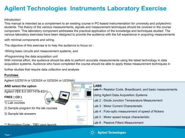
It’s all about plumbing... Once the transistor is there, the rest of the stuff (diodes, resistors, capacitors, conducting lines) in the circuit is simply used to give us better control over what the current does before and after it passes through our valve. In fact, ALL of our transistor processes (FET and HBT) are built using the same tool set: LITHOGRAPHY METAL DEPOSITION (EVAPORATION AND SPUTTERING) ION IMPLANTATION DIELECTRIC DEPOSITION WET AND DRY ETCHING OF METAL, DIELECTRIC, and SEMICONDUCTOR ELECTROPLATING LAPPING AND POLISHING
Lithography All of these devices are constructed layer by layer In some cases there are as many as 20 layers per circuit!!! Each layer has a “mask” defining the regions of interest. This mask is transferred to the wafer using a process called “lithography”
Lithography 2 STEP TWO: RESIST SPIN Photoresist is a light sensitive polymer that we spin on, cure and expose and develop, like film! STEP ONE: MASK PLATES (these are what circuit designers ultimately produce!) STEP FOUR: DEVELOP STEP THREE: UV EXPOSURE (in some cases, polymer cross-links in response to light, in others, it becomes more soluble)
Metal Deposition a) Evaporation b) Sputtering Trade-offs include deposition rate, substrate temperature, thickness and stoicheometry control, and metal profile
Lithography and Deposition - application For example: say I want to put down some metal on top of my substrate. Resist Spin – wafer held by a vacuum chuck and rotated (3000 rpm while a photosensitive liquid polymer is dispensed. Use a hard Chrome mask plate to expose (UV) and immerse in solution to develop away the resist We evaporate metal onto the surface (e-beam or resistive heating)) Then, dissolve away the photoresist with remaining metal, leaving metal just where we want it
“Just a little leak folks!” We’ll have ya all fixed up in a jiffy!” Dielectric Deposition (PECVD) See more about this on the next page! You’ll see both OXIDE and NITRIDE throughout the fab processes. These two layers are very important, mostly because we can use both of them to STOP current from flowing between metal layers. Often we use dielectrics to keep current from “leaking!” OXIDE
PECVD or Plasma Enhanced Chemical Vapor Deposition Dielectric forms when a combination of gases reacts at the surface of a wafer. For example, silane (SiO4) and nitrous oxide (N2O) dissociate, and the Si and O combine to form SiO2. We use a plasma to increase the rate of dissociation of the reacting molecules in the chamber.
Isolation As you know, METALS are REALLY good at conducting electricity. INSULATORS or DIELECTRICS are bad at conducting electricity. Si, Ge, and GaAs are semiconductors. That means they conduct … just not very well. We can use proton isolation to turn semiconductors into insulators in specific regions.
Isolation When we implant HYDROGEN ions (protons) into our semiconductor The area outside the pipe has been isolated! This area has NOT been implanted with hydrogen and current can pass through the semiconductor - if we want it to! The isolated field is now an EXCELLENT insulator!
Isolation Resist spin Expose and develop Implantation drives many many hydrogen ions into the unmasked areas (AND into the mask, but the mask protects the wafer surface) Strip the resist – Voila!
We can also make parts of semiconductors more conductive, by making “ohmic” contacts as opposed to “schottky” contacts GaAs is a semiconductor, so making “ohmic” contacts to GaAs is pretty tricky. We use an ALLOYED contact – made of Ti, Au, Ge, Ni, and – then cap it with oxide and heat it to force Ge to diffuse into the substrate. The Ge doping makes it easier for current to pass into and out of the semiconductor.
Ohmic Contacts to GaAs Au-Ge alloy systems are dominant for n-GaAs ohmic contacts Ti layer aids in oxide adhesion improving the ohmic contact, and is speculated to improve metal lift-off Thick Au over-layer enhances sheet conductivity, improves surface morphology, and enhances measurement accuracy Ti Au Ni Au eutectic composition of Au-Ge, co-deposited or evaporated in layers. (We evaporate in layers) Ge Ni layer historically described as a wetting agent. Possibly enhances Ge diffusion. Prevents AuGa clustering. Au epi-stack and substrate
Etching Wet Etching vs Dry Etching Wet Etching: the etch reactants come form a liquid source Dry Etching: the etch reactants come form a gas or vapor phase source and are typically ionized. Atoms or ions from the gas are the reactive species that etch the exposed film •Selectivity : In general, dry etching has less selectivity than wet etching •Anisotropy: In general, dry etching has higher degree of anisotropy than wet etching (exception being certain crystallographic etches) •Etch Rate: In general, dry etch has lower etch rate than wet etching •Etch Control: Dry etching is much easier to start and stop than wet etching NOTE: Dry etching is $$$$, but absolutely essential for high resolution or if you need deep vertical sidewalls.
Etching 2 MEMS (microelectromechanical systems) A pretty cool processing application! Triple-Piston Microsteam Engine Water inside of three compression cylinders is heated by electric current and vaporizes, pushing the piston out. Capillary forces then retract the piston once current is removed Courtesy Sandia National Laboratories, SUMMiTTM Technologies, www.mems.sandia.gov
Etching 3 In case you were wondering how small these things are from a different perspective Our gate features, by the way, are even smaller…. Courtesy Sandia National Laboratories, SUMMiTTM Technologies, www.mems.sandia.gov
The individual processes may seem straightforward, but we have to do some pretty crafty things to make them all come together!To make “gates” for example…
We need to use some pretty clever tricks… We use a “transfer layer” process to define the very tiny dimension of our gate stem. resist Ti / Au / Ti Photoresist nitride oxide n+GaAs AlGaAs
We then remove top Ti layer, electroplate Nickel, remove resist, wet etch plating base, and expose and develop resist. Whew!!!! .25um .55um resist nitride oxide n+GaAs AlGaAs
We then etch away the nitride and some of the oxide. .25um PMGI LERN SiO n+GaAs AlGaAs
We then chemically remove the plated Ni and Au layer, oxide (which also removes Ti), some of the GaAs and some of the AlGaAs. Now, FINALLY, the gates are ready to place. Note that they are being deposited on an AlGaAs layer. If we put them on any other layer there the current wouldn’t be able to pass through them! GATE PERFORMANCE IS HEAVILY DEPENDENT ON THE SHAPE AND FORMATION OF THIS RECESS!!!!!!! PMGI LERN SiO n+GaAs AlGaAs
We evaporate the gate metal PMGI nitride oxide n+GaAs AlGaAs
LERN SiO n+GaAs AlGaAs Then remove the Photoresist with remaining metal, leaving metal just where we want it Drain Source Gate
Now that we build ‘em, how do we know they work? We use a lot of different test along the way to make sure these parts actually work before they go out the door Each mask set has a corner of each reticle dedicated to an array of test devices. In fab, 20 devices are tested for a wide variety of parameters: “Critical” (RF tested 10GHz) parameters which define the performance of our transistors “DC” parameters which define the performance of our passive components Some tests are on-wafer screened for reliability.
T-chip Meanders to test inter-layer connectivity TLM for ohmic contact resistance Capacitor character-ization Transistor character-ization Test devices to target gate current Rel test chip Process monitor for gate stripe integrity
Conclusion We use a HUGE array of people to make and characterize devices: Electrical engineers Materials Engineers Chemical Engineers Mechanical Engineers Physicists Chemists Design Engineers A vast array of technicians and operators Managers Supervisors Planners Procurement experts Maintenance teams We all have our specialties, and we all work together!
Acknowledgements Agilent MWTC Don D’Avanzo Mathias Bonse Dan Thomasson