Download
1 / 25
270 likes | 459 Views
Atmospheric correction for the monitoring of land surfaces. Yoram J. Kaufman Symposium On Aerosols, Clouds and Climate, May 30, 31, and June 1, 2007, NASA GSFC. Eric F. Vermote Department of Geography, University of Maryland, and NASA GSFC code 614.5.

E N D
Atmospheric correction for the monitoring of land surfaces Yoram J. Kaufman Symposium On Aerosols, Clouds and Climate, May 30, 31, and June 1, 2007, NASA GSFC Eric F. Vermote Department of Geography, University of Maryland, and NASA GSFC code 614.5
AVHRR Vicarious Calibration(Vermote and Kaufman, 1995) Consistent and accurate calibration is a prerequisite to creating a long-term data record for climate studies. The AVHRR instrument suffers from the lack of onboard calibration for its visible to short wave infrared channels. Various vicarious calibration approaches were employed by users to account for the sensor degradation. For the LTDR REASoN project, we adopted the approach developed by Vermote and Kaufman (1995) that relies on clear ocean and accurate Rayleigh scattering computations to derive the sensor degradation in the red bands This approach uses high clouds to predict the variation in the near infrared (NIR) to Red ratio and transfer the calibration to the NIR channel
The calibration of the AVHRR has been thoroughly evaluated The coefficients were consistent within less than 1%
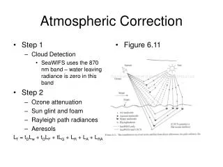
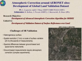
Surface Reflectance (MOD09) The Collection 5 atmospheric correction algorithm is used to produce MOD09 (the surface spectral reflectance for seven MODIS bands as it would have been measured at ground level if there were no atmospheric scattering and absorption). Goal: to remove the influence of • atmospheric gases - NIR differential absorption for water vapor - EPTOMS for ozone • aerosols - own aerosol inversion Home page: http://modis-sr.ltdri.org Movie credit: Blue Marble Project (by R. Stöckli)Reference: R. Stöckli, E. Vermote,N. Saleous, R. Simmon, and D. Herring (2006) "True Color Earth Data Set Includes Seasonal Dynamics", EOS, vol. 87(5), 49-55. www.nasa.gov/vision/earth/features/blue_marble.html 2
Basis of the AC algorithm • The Collection 5 AC algorithm relies on • the use of very accurate (better than 1%) vector radiative transfer modeling of the coupled atmosphere-surface system • the inversion of key atmospheric parameters (aerosol, water vapor) 3
Vector RT modeling The Collection 5 atmospheric correction algorithm look-up tables are created on the basis of RT simulations performed by the 6SV (Second Simulation of a Satellite Signal in the Solar Spectrum, Vector) code, which enables accounting for radiation polarization. May 2005: the release of a β-version of the vector 6S (6SV1.0B) . . . . . . . . . . . . . . . . . . . . . . . . . . . . . . . . . . . . . . . . . . . . . . . . . . . . e x t e n s i v e v a l i d a t i o n a n d t e s t i n g . . . . . . . . . . . . . . . . . . . . . . . . . . . . . . . . . . . . . . . . . . . . . . . . . . . . . May 2007: the release of version 1.1 of the vector 6S (6SV1.1) 4
6SV Validation Effort • The complete 6SV validation effort is summarized in two manuscripts: • S. Y. Kotchenova, E. F. Vermote, R. Matarrese, & F. Klemm, Validation of a vector version of the 6S radiative transfer code for atmospheric correction of satellite data. Part I: Path Radiance, Applied Optics, 45(26), 6726-6774, 2006. • S. Y. Kotchenova & E. F. Vermote, Validation of a vector version of the 6S radiative transfer code for atmospheric correction of satellite data. Part II: Homogeneous Lambertian and anisotropic surfaces, Applied Optics, in press, 2007. 6
Key atmospheric parameters Vector 6S LUTs AC algorithm coarse resolution meteorological data MODIS calibrated data Input Data for Atmospheric Correction • surface pressure • ozone concentration • column water • aerosol optical thickness (new) Reference: Vermote, E. F. & El Saleous, N. Z. (2006). Operational atmospheric correction of MODIS visible to middle infrared land surface data in the case of an infinite Lambertian target, In: Earth Science Satellite Remote Sensing, Science and Instruments, (eds: Qu. J. et al), vol. 1, chapter 8, 123 - 153. 15
Error Budget (collection 4) Goal: to estimate the accuracy of the atmospheric correction under several scenarios 16
Overall Theoretical Accuracy Overall theoretical accuracy of the atmospheric correction method considering the error source on calibration, ancillary data, and aerosol inversion for 3 τaer = {0.05 (clear), 0.3 (avg.), 0.5 (hazy)}: The selected sites are Savanna (Skukuza), Forest (Belterra), and Semi-arid (Sevilleta). The uncertainties are considered independent and summed in quadratic. 27
Original approach: “dark and dense vegetation (DDV) technique” a linear relationship between ρVIS and ρNIR limitation to the scope of dark targets refined approach: a more robust “dark target inversion scheme” a non-linear relationship derived using a set of 40 AERONET sites representative of different land covers can be applied to brighter targets Retrieval of Aerosol Optical Thickness 20
Collection 5 Aerosol Inversion Algorithm Pioneer aerosol inversion algorithms for AVHRR, Landsat and MODIS (Kaufman et al.) (the shortest λ is used to estimate the aerosol properties) • Refined aerosol inversion algorithm • use of all available MODIS bands (land + ocean, e.g. 412nm as in Deep Blue) • improved LUTs • improved aerosol models based on the AERONET climatology • a more robust “dark target inversion scheme” using Red to predict the blue reflectance values (in tune with Levy et al.) • inversion of the aerosol model (rudimentary) 22
Example 1: RGB (670 nm, 550 nm, 470 nm) Top-of-atmosphere reflectance RGB (670 nm, 550 nm, 470 nm) Surface reflectance 23
490 nm 470 nm 443 nm 412 nm 0.5 0.2 0.4 Aerosol Optical Depth Example 1: Red (670 nm) Top-of-atmosphere reflectance 24
RGB (670 nm, 550 nm, 470 nm) Surface reflectance Example 2: AOT= 0.896 (7km x 7km) Model residual: Smoke LABS: 0.003082 Smoke HABS: 0.004978 Urban POLU: 0.04601 Urban CLEAN: 0.006710 RGB (670 nm, 550 nm, 470 nm) Top-of-atmosphere reflectance 25
RGB (670 nm, 550 nm, 470 nm) Surface reflectance Example 3: AOT= 0.927 (7km x 7km) Model residual: Smoke LABS: 0.005666 Smoke HABS: 0.004334 Urban POLU: 0.004360 Urban CLEAN: 0.005234 RGB (670 nm, 550 nm, 470 nm) Top-of-atmosphere reflectance 26
Performance of the MODIS C5 algorithms To evaluate the performance of the MODIS Collection 5 algorithms, we analyzed 1 year of Terra data (2003) over 127 AERONET sites (4988 cases in total). Methodology: Subsets of Level 1B data processed using the standard surface reflectance algorithm comparison Reference data set Atmospherically corrected TOA reflectances derived from Level 1B subsets If the difference is within ±(0.005+0.05ρ), the observation is “good”. AERONET measurements (τaer, H2O, particle distribution) Vector 6S http://mod09val.ltdri.org/cgi-bin/mod09_c005_public_allsites_onecollection.cgi 28
Validation of MOD09 (1) Comparison between the MODIS band 1 surface reflectance and the reference data set. The circle color indicates the % of comparisons within the theoretical MODIS 1-sigma error bar: green > 80%, 65% < yellow <80%, 55% < magenta < 65%, red <55%. The circle radius is proportional to the number of observations. Clicking on a particular site will provide more detailed results for this site. 29
Validation of MOD09 (2) Example: Summary of the results for the Alta Foresta site. Each bar: date & time when coincident MODIS and AERONET observations are available The size of a bar: the % of “good” surface reflectance observations Scatter plot: the retrieved surface reflectances vs. the reference data set along with the linear fit results 30
Validation of MOD09 (3) Nes Ziona site (92.86%) Scatter plot: the retrieved surface reflectances vs. the reference data set along with the linear fit results 30
Validation of MOD09 (3) In addition to the plots, the Web site displays a tablesummarizing the AERONET measurementand geometrical conditions, and shows browse images of the site. MOD09-SFC Percentage of good: band 1 – 86.62% band 5 – 96.36% band 2 – 94.13% band 6 – 97.69% band 3 – 51.30% band 7 – 98.64% band 4 – 75.18% Similar results are available for all MODIS surface reflectance products (bands 1-7). 31
Validation of MOD13 (NDVI) Comparison of MODIS NDVI and the reference data set for all available AERONET data for 2003. Globally, 97.11% of the comparison fall within the theoretical MODIS 1-sigma error bar (±(0.02 + 0.02VI)). green > 80%, 65% < yellow <80%, 55% < magenta < 65%, red <55% 32
Validation of MOD09 (EVI) Comparison of MODIS EVI and the reference data set for all available AERONET data for 2003. Globally, 93.64% of the comparison fall within the theoretical MODIS 1-sigma error bar (±(0.02 + 0.02VI)). green > 80%, 65% < yellow <80%, 55% < magenta < 65%, red <55% 33
Generalization of the approach for downstream product (e.g., Albedo) 34
Land Cover Thermal Anomalies BRDF/Albedo Burned Areas LAI/FPAR VI Snow Cover MOD09 Applications Surface Reflectance 36