Download
1 / 13
360 likes | 1.1k Views
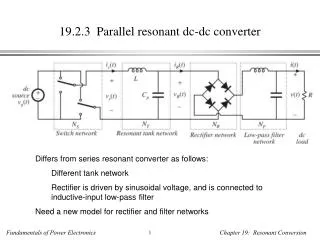
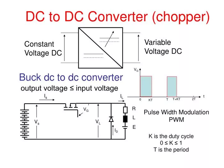
Variable Voltage DC. Constant Voltage DC. DC to DC Converter (chopper). V G. Buck dc to dc converter. output voltage ≤ input voltage. I s. I L. t. 2T. T+KT. 0. T. KT. R. V G. Pulse Width Modulation PWM. L. V L. V s. E. I D. K is the duty cycle 0 ≤ K ≤ 1 T is the period.

E N D
Variable Voltage DC Constant Voltage DC DC to DC Converter (chopper) VG Buck dc to dc converter output voltage ≤ input voltage Is IL t 2T T+KT 0 T KT R VG Pulse Width Modulation PWM L VL Vs E ID K is the duty cycle 0 ≤ K ≤ 1 T is the period
For 0 ≤ ωt ≤ KT iL= (Vs – E) / R + A exp-(t/ζ) Where ζ = L/R iL= Imin @ ωt = 0 Imin = (Vs-E) /R + A A = Imin – (Vs-E) / R iL= (Vs – E) / R + [ Imin – (Vs-E) / R ] exp-(t/ζ) iL= Imax @ωt = KT Imax=(Vs – E) / R + [Imin – (Vs-E) / R] exp-(KT/ζ) ..(1) For KT ≤ ωt ≤ T iL= - E/R + B exp-[(t-KT)/ζ)] iL= Imax @ ωt = KT Imax= - E/R + B B = Imax + E/R iL= - E/R + (Imax + E/R) exp-[(t-KT)/ζ)] iL= Imin @ ωt = T Imin= - E/R + (Imax + E/R) exp-[(T-KT)/ζ].. (2) Substituting from (1) into (2): Imin= - E/R + {(Vs – E) / R + [ Imin – (Vs-E) / R ] exp-(KT/ζ)+ E/R} exp-[(T-KT)/ζ)] Imin[1 – exp-(T /ζ)] =Vs/R { exp-[(T-KT)/ ζ] -exp-(T /ζ)} – E/R {1+exp-[(T-KT)/ ζ]- exp-(T /ζ) -exp [(T-KT)/ζ)] } Assuming continuous load current
iL Imax Imin`` t t T+KT T+KT 0 0 KT KT T T vL Vs Imin[1 – exp-(T /ζ)] =Vs/R { exp-[(T-KT)/ ζ] + exp-(T /ζ) } – E/R {1-exp-[(T-KT)/ ζ]- exp-(T /ζ) - exp [(T-KT)/ζ)] } Imin= vs exp-[(T-KT)/ ζ] - exp-(T /ζ) } - E R 1 – exp-(T/ ζ) R Imin= Vs exp(KT/ ζ) -1 - E R exp (T/ζ) – 1 R Substituting for Imin in (1): Imax=(Vs – E) + [ Vs exp(KT/ ζ) -1 - E – Vs-E ] exp-KT/ζ) R R exp(T/ζ) -1 R R Imax= Vs [ 1 + 1 - exp-(KT/ζ) - exp-(KT/ζ)] - E R exp(T/ζ) - 1 R Imax= Vs exp(T/ζ) - 1 + 1 - exp-(KT/ ζ) - exp[(T-KT)/ζ] + exp-(KT/ ζ) - E R exp(T/ζ) - 1 R Imax= Vs exp (T/ζ) - exp (T-KT/ ζ) - E R exp (T/ζ) - 1 R Imax= Vs 1 – exp-(KT/ ζ) - E R 1 – exp- (T/ζ) R VLav= K Vs
Imax t KT T+KT T For discontinuous load current conduction iL For 0 ≤ t ≤ KT i = (Vs-E) / R + A exp-(t/ζ) i = 0 @ t = 0 0 = (Vs-E) / R + A A = - (Vs-E) / R i = (Vs-E) / R [ 1 – exp-(t/ζ) ] i = Imax @ t = KT Imax = (Vs-E) / R [ 1 – exp-(KT/ζ) ] For KT ≤ t ≤ tx i = - (E/R) + B exp-[(t-KT)/ζ] i = Imax @ t = KT Imax= (E/R) + B B = Imax + E/R t tx T+tx KT T+KT 0 T vL Vs E tx T+tx VLav= K Vs + [(T-tx)/T] E B = (Vs-E) / R [ 1 – exp-(KT/ζ) ] + E/R = Vs/R – Vs/R exp-(KT/ζ) + E/R exp-(KT/ζ) i = - E/R + {Vs/R – Vs/R exp-(KT/ζ) + E/R exp-(KT/ζ)} exp-[(t-KT)/ζ] i = - E/R + Vs/R exp-[(t-KT)/ ζ] – Vs/R exp-(t/ζ) + E/R exp-(t/ζ)..(1) i = 0 @ t = txx 0 = - E + exp-(tx/ζ) { [ Vs exp(KT/ζ) – Vs + E } E exp-(tx/ζ) = Vs exp(KT/ζ) – Vs + E
exp (tx/ζ) = Vs/E exp(KT/ζ) – Vs/E + 1 tx = ζ ln { Vs/E [ exp(KT/ζ) – 1 ] + 1 } To calculate the critical duty cycle ratio Kcri, corresponding to critical conduction by substituting into (1) by K = Kcri , tx = T and i = 0 : 0 = - E/R + Vs/R exp-[(T-KcrT)/ ζ] – Vs/R exp-(T/ζ) + E/R exp-(T/ζ) Vs exp-[(T-KcriT)/ ζ] = E + Vs exp-(T/ζ) - E exp-(T/ζ) Vs exp(KcriT/ζ) = E exp(T/ζ) + Vs - E exp(KcriT/ζ) = E/Vs exp(T/ζ) + 1 - E/Vs Kcri= ζ/T ln[ 1 + E/Vs (exp(T/ζ) -1) ] iL Imax t 0 KcriT T T+KcriT
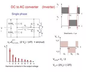
Load characteristics of a dc to dc converter VL K=1 K=0.8 K=0.6 Continuous conduction Discontinuous conduction K=0.4 K=0.2 IL
KT KT T+KT T+KT 2T 2T T T 0 0 vG1 2-quadrant dc to dc converter Is IL D2 R VG1 t T1 T2 L Vs VL D1 E VG2 vG2 • No discontinuous load current since there is a pathe • for negative load current through T2 if conducting. • 3 cases are present: • ILmax & ILmin are both +ve • ILmax is +ve & ILmin is –ve • ILmax & ILmin are both –ve t Complementary control for T1 & T2 IL VL
t t T+KT T+KT 0 0 KT KT T T iL Imax 1st case: ILmax& ILmin are both +ve Imin`` Is IL D2 vL R VG1 Vs T1 T2 L Vs VL D1 E VG2 In this case the circuit acts exactly like a single quadrant dc to dc converter, no current flows through T2 or D2 . During the interval from 0 to KT, power is transferred from Vs to the load. During the interval from KT to T, power stored in L is dissipated in the R and the forward resistance of D1 if considered.
t T+KT 0 KT T iL 1st case: Imax & Imin are both +ve Imax i2 i2 i1 i1 Imin`` i1 i1 D2 R VG1 T1 T2 L Vs VL D1 E VG2 i1 i1 i2 D2 R VG1 T1 T2 L VL Vs D1 E i2 VG2 i2
i3 i4 D2 R VG1 T1 T2 L Vs VL D1 E i4 VG2 i4 iL i3 i3 D2 Imax i4 i4 i1 i1 t R VG1 i3 i3 Imin`` T1 i2 i2 T2 L Vs VL T+KT 0 KT T D1 E VG2 i3 i1 i1 D2 i3 R VG1 T2 T1 L Vs VL D1 E VG2 i1 i1 i2 D2 R VG1 T1 T2 L Vs D1 E i2 VG2 i2 2nd case: Imax is +ve & Imin is -ve
i2 D2 R VG1 T1 T2 L Vs D1 E i2 VG2 i2 3rdcase: Imax & Imin are both -ve i1 i1 i1 D2 R VG1 T1 T2 L Vs VL D1 E 0 VG2 T+KT KT T i1 t Imax i2 i2 i1 i1 i1 Imin`` Note that the load must be active such that it can support negative load current with a positive supply voltage Vs.
E R L IL 4-quadrant dc to dc converter IL T1 T3 D2 D4 VG1 VG3 Vs VL T2 T4 D1 D3 VG2 VG4 Operation in the 1st and 4th quadrants Operation in the 2nd and 3rd quadrants vG1 vG3 vG1 vG3 IL t t t t T T+KT T T+KT 0 KT KT 0 T T+KT KT 0 T T+KT 0 KT vG3 vG2 vG2 vG4 t t t T T+KT KT t 0 T T+KT 0 KT T T+KT KT 0 T T+KT 0 KT