Download
1 / 25
250 likes | 375 Views
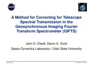
Ground and On-Orbit Characterization and Calibration of the Geosynchronous Imaging Fourier Transform Spectrometer (GIFTS). John D. Elwell 1 , Deron K. Scott 1 Henry E. Revercomb 2 , Fred A. Best 2 , Robert O. Knuteson 2

E N D
Ground and On-Orbit Characterization and Calibration of the Geosynchronous Imaging Fourier Transform Spectrometer (GIFTS) John D. Elwell1, Deron K. Scott1Henry E. Revercomb2, Fred A. Best2, Robert O. Knuteson2 1Space Dynamics Laboratory / Utah State University2University of Wisconsin-Madison, Space Science and Engineering Center Calcon 2003 September 15-18, 2003
Purpose of Calibration & Characterization • Verify that GIFTS meets its fundamental radiometric absolute accuracy specification of <1 K (3) brightness temperature for remote sensing and climate applications • Provide a complete instrument characterization • Measure instrument responses independently in each domain (radiometric, spectral, spatial, etc.) • Characterize intra-domain responses • Quantify inter- and intra-domain characteristics as a function of time • Estimate uncertainties • Provide numerical results for downstream data processing (instrument products (IPs)) September 15-18, 2003
GIFTS Specifications • Two IR focal planes • Short/midwave - 4.4 to 6.1 mm • Longwave - 8.8 to 14.6 mm • 128 x 128 pixels, 4-km pixel footprints at nadir • 7 spectral resolutions from 0.6 cm-1 to 38 cm-1 • Visible focal plane • 0.5 to 0.8 mm • 512 x 512 pixels, 1-km pixel footprints at nadir • All three focal planes are co-aligned • Pointing mirror provides 12 x 12 degree field for coverage of earth as well as viewing cold space September 15-18, 2003
Calibration and Characterization • Ground calibration and characterization will be performed at SDL using the MIC2 calibrator and a separate high-accuracy extended source, coupled with the GIFTS test chamber • On-orbit calibration will be done throughout mission life • Two in-flight calibrators (IFCs) will provide radiometric calibration • Celestial sources will allow goniometric calibration • Atmospheric lines will allow spectral calibration update • All critical and time-dependent instrument products will be updated on-orbit to maintain accuracies throughout the life of GIFTS September 15-18, 2003
Ground Calibration Challenges • Data Volume • One high resolution scan (11 seconds) creates 200 megabytes of data and 32,768 complex interferograms • A typical data collection event of 100 high-resolution scans collected in 18 minutes would fill 41 CD-ROMs or 6 DVD-ROMs • Data Validation • The large data volumes require automated verification that the data collected is correct before moving to the next test setup • Data Reduction • Where possible, a subset of pixels will be analyzed and the results generalized to all pixels, e.g. PRFs, distortion map, polarization responses • However, some instrument products will need to be calculated on a per-pixel basis September 15-18, 2003
Ground Calibration Configuration • GIFTS will be installed in a test chamber that will simulate on-orbit operating conditions • Sources can be changed without the need to cryo-cycle GIFTS • The SDL multifunction infrared calibrator (MIC2) calibrator will be used for spectral and spatial calibrations • The SDL high accuracy extended source will be used for absolute radiometric calibrations • Source temperature: 77 to 350 K, emissivity: 0.999 • Absolute radiance uncertainty • Short/midwave: 0.45% from 190 – 300 K • Longwave: 0.22% from 190 – 300 K September 15-18, 2003
MIC2 Configurations Collimator Source Extended Source Jones Source Scatter Source September 15-18, 2003
Daily Benchmark • Characterizes repeatability of spectral radiance responsivity, offsets, and noise • Data will be collected daily throughout calibration under similar conditions • Configuration: • Extended source (MIC2 or high accuracy extended source) • In-flight calibrators • Cold background (cold shutter in the MIC2 or extended source) • Dark offset and electronic offset September 15-18, 2003
Linearity • Characterizes the nonlinear response of the IR focal planes throughout their dynamic range • Determined for all pixels • Configuration: • MIC2 Jones source with an external blackbody and chopper will provide a constant level AC flux • MIC2 extended source will provide a background flux from below noise to saturation • Interferometer carriage is stopped and the DC and AC components of the combined flux sources are recorded September 15-18, 2003
Polarization Response • Characterizes spectral responsivity as a function of variable polarization input flux • Analyzed for a subset of pixels • Will allow modeling of polarization sensitivity to apply a first-order correction of responsivity changes as a function of the pointing mirror angle • Configuration: • MIC2 with an external blackbody and polarizer to collect data with the input flux polarized at steps over 360 degrees • Repeated at several locations over the field-of-regard September 15-18, 2003
Spatial Calibration • Characterizes point response functions, ensquared energy, near field scatter, optical distortion, and co-alignment of the two IR and one visible focal planes • Configuration: • MIC2 collimator and a cold aperture to provide an unresolved point source for the IR focal planes • Large aperture (~ 4 IR pixels in diameter) to allow calculation of the centroid of energy to subpixel resolutions • Source that simultaneously produces a response in all three focal planes • Data collected for a subset of detectors across the focal plane September 15-18, 2003
Spectral Line Shape and Position • Characterizes instrument line shape, position of the line on a wavenumber scale, and estimate of position error • Configuration: • MIC2 scatter plate to illuminate the focal planes • Strong line source from IR lasers and/or an external blackbody and absorption cell • Data collected with line(s) within the passband of both IR focal planes September 15-18, 2003
Responsivity & Temperature Effects • Characterizes spectral radiance responsivity and noise over the dynamic range, spectral radiance responsivity as a function of focal plane temperature, and compares the external extended source to the in-flight calibrators • Configuration: • High-accuracy extended source • Extended source shutter • Responsivity data collected over the expected range of FPA temperatures September 15-18, 2003
Telescope Background • Characterizes telescope radiance model and uncertainties to derive telescope emissivity and transmission • Configuration: • Cold target • Internal flight calibrators September 15-18, 2003
Saturation and Crosstalk • Characterizes saturation recovery and crosstalk effects from saturated to unsaturated pixels • Configuration: • High-accuracy extended source and cold shutter • MIC2 collimator with a hot external blackbody September 15-18, 2003
Miscellaneous Tests • Far-field characterization • Subpixel characterization • Sampling mode characterization • Out-of-band responsivity • Medium term repeatability September 15-18, 2003
Ground Calibration Data Collection Calibration Data Volume Collection Test (Gbytes, compressed) Time (hours) Daily Benchmarks 12 (daily) 1 (daily) Linearity 17 9 Spectral Radiance Responsivity 365 22 SRR as f(FPA Temp) 30 22 Polarization 59 20 Telescope Background 141 36 Spatial Characterizations 66 18 Far Field Scatter 35 9 Spectral Line Shape/Position 71 13 Saturation & Temporal 33 14 Misc. tests 344 53 Totals approx. 1100 Gbytes appox. 27 days GIFTS & Source Prep Time (approx. 16 days) September 15-18, 2003
On-Orbit Calibration Experiments • Calibration sequence • Collects electronic offset, dark offset, cold space, visible stim, and IFC data • Provide radiance calibration data and other instrument products • Telescope tests • Updates telescope transmission and flip-in mirror reflectance for changes on-orbit • Subpixel validation • Improves IR LW FPA operability by selectively enabling subpixels September 15-18, 2003
On-Orbit Calibration Experiments • Star scans over the FOV, FOR • Provide pointing calibration information within the field of view and field of regard • Calibration reproducibility • Determine the allowable time between calibration sequences to maintain radiometric accuracies • Solar loading and transition zone • Provide knowledge of how the instrument will perform, radiometrically and spatially, during the solar loading cycle September 15-18, 2003
UW-SSEC GIFTS On-Orbit Radiometric Calibration Concept • Two small reference blackbodies located behind telescope, combined with space view • The combination of the internal blackbodies and the space view allow tracking of any in-flight changes of the fore-optics transmission • Blackbody design is scaled from the UW ground-based AERI and NAST/S-HIS aircraft instruments. (Best et al., CALCON 2003) • Advantages compared to large external blackbody: (1) Higher emissivity is practical with small size (2) Protection from solar forcing (3) Mass and volume savings (4) Smaller range of pointing angles September 15-18, 2003
Radiance N derived from raw spectra of earth (CE), space (CS), and the internal hot (CH) and cold (CC) blackbodies t is the signal transmission of the telescope mirrors andm is the transmission of the blackbody pick-off mirror B is the Planck radiance from the hot, cold, and space references UW-SSEC GIFTS Radiometric Calibration Concept September 15-18, 2003
UW-SSEC GIFTS Calibration Accuracy Longwave (1000 cm-1) Requirement GIFTS Baseline Shortwave (2000 cm-1) Requirement GIFTS Baseline September 15-18, 2003
UW-SSEC GIFTS On-Orbit Spectral Calibration • Primary issue to be addressed by the spectral calibration is wavenumber scale “stretch” across the array • Instrument line shape effects are negligible because of the small angular size of individual pixels • The wavenumber scale stretch variation over the array is large, but is physically well understood and can easily be removed using known positions of absorption lines • Pre-flightspectral calibration parameters determined during ground calibration • Highly stable laser serves as an in-flight calibration reference • Verify in-flight using known atmospheric absorption lines See Dave Tobin’s Presentation (CALCON 2003) September 15-18, 2003
Calibration DCE Times and Volumes September 15-18, 2003