Download
1 / 47
470 likes | 560 Views
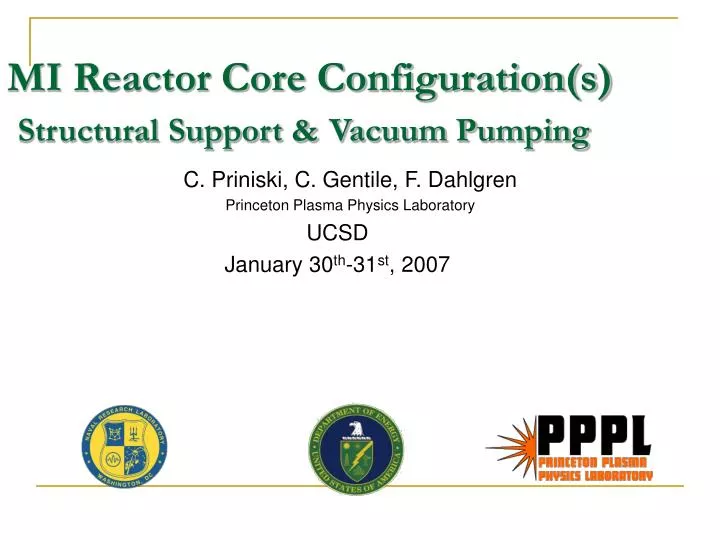
MI Reactor Core Configuration(s) Structural Support & Vacuum Pumping. C. Priniski, C. Gentile, F. Dahlgren Princeton Plasma Physics Laboratory UCSD January 30 th -31 st , 2007. 10 m. Current Thinking:. A.E. Robson 1/26/07. John Sethian MI Chamber 1/23/07. PPPL HAPL 16 Configuration.

E N D
MI Reactor Core Configuration(s)Structural Support &Vacuum Pumping C. Priniski, C. Gentile, F. Dahlgren Princeton Plasma Physics Laboratory UCSD January 30th-31st, 2007
10 m Current Thinking: A.E. Robson 1/26/07 John Sethian MI Chamber 1/23/07
Vacuum Vessel StructureInternal Component Approximate Weights 17Li-83Pb Conical Blanket: Density of Breeder: 8650 kg/m^3 1 Blanket volume: ~130.6 m3 Blanket weight: 1.12 million kg, or 1,245 tons FliBe Conical Blanket: Density of Breeder: ~1990 kg/m32 Blanket volume: ~same 130.6m3 Blanket weight: 260,000 kg, or 287 tons Internal Neutron Shielding 75% weight steel: Weighing about 252,000 kg, or 278 tons 1. ITER Documentation Series No 29, IAEA, Vienna 1991 "Blanket, Shield Design and material Data Base. 2. Proposal of a Blanket concept based on FliBe and advanced ferritic steel, APEX Meeting , San Diego, April 17-19 , 2002
Vacuum Vessel StructureFEA Analysis Upper Shell SST Under Vacuum & Structural Loads Total deflection ~ 8 mm for 1.5 inch thick vessel
Chamber Maintenance • Accomplished through domed (upper and lower) flange diameter allows removal of small coil • Four laser ducts removed (all optics remain in place) • Requires modular consumable components (blanket, ion dumps) • Allows for toriodal ion dump vacuum pumping
16th HAPL - Magnetic Intervention Chamber • General conceptual arrangement for the magnetic intervention chamber
Baseline Design of Cusp Coils • Cable in Conduit Conductor (CICC) comprised of Nb-Ti superconductor with a forced flow super-critical LHe coolant • High current density option is considered if AC fields are not present in the coil windings and a much lower current density configuration if a 5 Hz AC field is present (currently under investigation) • Coil and case will be force-cooled with 4.5-5 K LHe • An additional LN2 shroud will be positioned around the coil structure and support columns to be a thermal shield • Radiation and neutronics studies* suggest that a minimum 50 cm thick water/316L-SS shield required between SiC blanket and coil • Other coil conductor options, including use of Rutherford cable and HTS YBCO are also under consideration *per M. Sawan, U.W., HAPL Meeting, GA, August 8-9, 2006 Typical CICC Nb-Ti Conductor for ITER
Alternate conductors A typical Rutherford-type cable (NbTi) is used in most HEP S.C. coils Figure 2.11*: The LHC Rutherford cable for the outer layer of the main dipole magnets, quadrupole magnets and busbars: 36 strands, width 15.1mm, (1.9K, 9tesla)12900A, =19.2442mm, strand twist pitch 10.5cm. A short longitudinal section is shown on the top; the trapezoidal cross-section on the bottom. Jtyp = 1.2-1.7kA/sq.mm I = 12kA/cable * A. Devred. Superconductor development in europe. Proceedings of the Workshop on VLHC Magnets, FNAL, 2000.
Alternate conductors HTS offers the promise of higher fields, current densities, & 77 oK operation Currently YBCO S.C. is available in 20meter lengths with Cu stabilized 3-ply or with Stainless 3-ply construction. AMSC is projecting km lengths by late ‘07 Compiled by P.Lee, et.al., U.Wisconsin, FSU, NHFML • Higher heat capacity @ 77K should reduce (eliminate?) requirements for quench protection/detection. • Current commercial application: Synchronous Condensers for power industry
Alternate conductors • MgB2 is a mid-temperature range S.C. (up to 39 K) • Practical conductor lengths are becoming available • (1-4 km) in quantity (Hyper Tech anticipates their production capacity to be >500 km/yr. this year). • Columbus S.C.,SpA of Genoa Italy has produced 18km of S.C. in >1.5 km lengths for an open MRI magnet. • Has the advantages of high thermal margin & lower cost than NbTi or Nb3Sn conductors. • Jc = 320 A/sq.mm @ 20 K - 4Tesla. Hyper-Tech MgB2 Conductor Columbus MgB2 Conductor - ASG Hyper Tech Research, Inc. info.:
Alternate conductors ITER Nb3Sn CICC
Cusp Field Coil Analysis COIL A Z NI FZ FR/L FZ/L S-HOOP COMBINED M M AT N N/M N/M N/M SQ STRESS IN IN AT LB LB/IN LB/IN PSI PSI DFL-R 1 3.400 5.000 4.000E+06 -8.105E+06 2.660E+06 -3.794E+05 1.159E+07 133.858 196.850 4.000E+06 -1.823E+06 1.520E+04 -2.168E+03 1.682E+03 1.912E+03 1.407E-02 2 3.400 -5.000 -4.000E+06 8.106E+06 2.660E+06 3.794E+05 1.159E+07 133.858 -196.850 -4.000E+06 1.823E+06 1.520E+04 2.168E+03 1.682E+03 1.912E+03 1.407E-02 3 6.100 2.250 4.800E+06 4.511E+07 9.559E+05 1.177E+06 7.472E+06 240.157 88.583 4.800E+06 1.015E+07 5.461E+03 6.723E+03 1.084E+03 3.537E+03 1.627E-02 4 6.100 -2.250 -4.800E+06 -4.511E+07 9.559E+05 -1.177E+06 7.472E+06 240.157 -88.583 -4.800E+06 -1.015E+07 5.461E+03 -6.723E+03 1.084E+03 3.537E+03 1.627E-02 • Axial (vertical) loads = 8.1 MN on the smaller coils, = 45.1 MN on the larger radius coil set. • Coils would be self supporting against radial loads • Coil weight = 35 tons for 3.4 Meter coils, 61 tons for 6 Meter radius, 192 tons total (4 coils) • Inductance: Coil#1 = 0.0171 henries, Coil#2 = 0.0396 henries • Stored energy: Coil#1 = 5.5 MJ, Coil#2 = 45.6 MJ • Cryogen refrigeration (wag) ~ 1-2kW, ~10kg/hr (rad. Heating?)
Very rough cost estimate of Cusp Coils • A rough cost estimate of coil fabrication NbTi $ 350/lb 15% OFHC Cu $ 3.12/lb 65% Jacket $ 180/lb 20% Coil Fabr. $ 1100/lb • Additional costs for instrumentation, coil design and joint development, quench protection, and structural support, cryo-plant, plumbing, power supplies, etc. TFC =184000(350*0.15+180*0.20+3*0.65) + 1100*184000 = 219 M$ * Table I-3a From: M.I.T. Plasma Science and Fusion Center Report PSFC/RR-99-6
Conclusions and Path Forward • Investigate conceptual design of a magnet system which will produce a sufficient cusp shaped field for the deflection of the charged products from a direct drive inertial fusion target • Further refinements of the design will address: • radiation/lifetime • structural supports • busing/joint configuration • fault and quench protection • cryogen & refrigeration requirements • feasibility and economies of alternative conductor options
ITER- Cost Info 10 B$ machine cost ~1/2% PF2 (2coils) .005x10e9 = 50M$ For NbTi conductor for PF-2 coil only Assume another 60-70M$ for fabrication 120M$ for two coils
Relative S.C. cost in $/kA-Meter Alternate conductors -costs Current cost 10-year Projected cost • NbTi • ~1.5 $/kA m 0.76 $/kA m (@ 5T) • Nb3Sn • ~15 $/kA m 4 $/kA m • YBCO • ~200 $/kA m (‘06) 50$/kA m (by ‘08?) • Possible cost/kg 5-10 years out: • Niobium-based: ~$160/kg ($350/lb) • MgB2 <$50/kg ($110/lb) ?, <$0.10/m
Nb-Ti: Example of Best Industrial Scale Heat Treated Composites ~1990 (compilation) Critical Current Density, A/mm² Nb-Ti(Fe): 1.9 K, Full-scale multifilamentary billet for 10,000 FNAL/LHC (OS-STG) ASC'98 At 4.2 K Unless Nb-44wt.%Ti-15wt.%Ta: at 1.8 K, monofil. high field Otherwise Stated optimized, unpubl. Lee et al. (UW-ASC) ‘96 Nb-Ti 2 K Nb-Ti-Ta Nb-37Ti-22Ta: at 2.05 K, 210 fil. strand, 400 h total HT, Chernyi et al. (Kharkov), ASC2000 Nb Sn Internal Sn 3 2212 Round Wire Nb3Sn: Bronze route VAC 62000 filament, non-Cu 0.1µW·m 1.8 K Jc, VAC/NHMFL data courtesy M. Thoener. Nb3Sn: Non-Cu Jc Internal Sn OI-ST RRP #6555-A, 0.8mm, 1,000 LTSW 2002 2223 Nb3Al: Nb stabilized 2-stage JR process (Hitachi,TML- Nb Al 3 Nb Al NRIM,IMR-TU), Fukuda et al. ICMC/ICEC '96 ITER 3 Nb3Al: JAERI strand for ITER TF coil 100 1.8 K Nb-Ti-Ta Bi-2212: non-Ag Jc, 427 fil. round wire, Ag/SC=3 (Hasegawa ASC2000+MT17-2001) 1.8 K Nb Sn Bi 2223: Rolled 85 Fil. Tape (AmSC) B||, UW'6/96 3 Bronze Process Bi 2223: Rolled 85 Fil. Tape (AmSC) B|_, UW'6/96 10 0 5 10 15 20 25 30 Applied Field, T Super Conductors Advancing Critical Currents in Superconductors University of Wisconsin-Madison Applied Superconductivity Center December 2002 - Compiled by Peter J. Lee
Nb-Ti: Max @4.2 K for whole LHC NbTi strand production (CERN-T. Boutboul) Nb-Ti: Max @1.9 K for whole LHC NbTi strand production (CERN, Boutboul) Nb-Ti: Nb-47wt%Ti, 1.8 K, Lee, Naus and Larbalestier UW-ASC'96 Nb-37Ti-22Ta, 2.05 K, 50 hr, Lazarev et al. (Kharkov), CCSW '94. Nb3Sn: Non-Cu Jc Internal Sn OI-ST RRP 1.3 mm, ASC'02/ICMC'03 Nb3Sn: Bronze route int. stab. -VAC-HP, non-(Cu+Ta) Jc, Thoener et al., Erice '96. Nb3Sn: 1.8 K Non-Cu Jc Internal Sn OI-ST RRP 1.3 mm, ASC'02/ICMC'03 Nb3Al: JAERI strand for ITER TF coil Nb3Al: RQHT+2 At.% Cu, 0.4m/s (Iijima et al 2002) Bi-2212: non-Ag Jc, 427 fil. round wire, Ag/SC=3 (Hasegawa ASC-2000/MT17-2001) Bi 2223: Rolled 85 Fil. Tape (AmSC) B||, UW'6/96 Bi 2223: Rolled 85 Fil. Tape (AmSC) B|_, UW'6/96 YBCO: /Ni/YSZ ~1 µm thick microbridge, H||c 4 K, Foltyn et al. (LANL) '96 YBCO: /Ni/YSZ ~1 µm thick microbridge, H||ab 75 K, Foltyn et al. (LANL) '96 MgB2: 4.2 K "high oxygen" film 2, Eom et al. (UW) Nature 31 May '02 30 MgB2: Tape - Columbus (Grasso) MEM'06 References slide#9: ITER IFDA mtg. Geneva,7 June’06-A.Portone,E.Salpeitro Bromberg, L., Shultz,J., - Aries Stellerator Talk Lee,P. - UW, Madison, NHMFL (compiled slide#9) Devred, A. Superconductor development in europe. Proceedings of the Workshop on VLHC Magnets, FNAL, 2000. American Supercon, Inc. Columbus S.C.,SpA Hyper Tech Research, Inc.
Chambers Evaluated for VPS 6.5m Toroidal Duct (MI 1.0) 11m Laser Ports (BDC) 5m Plenum Ducts (FTF) Advanced MI Chamber Laser Ports 1.29*106 liters 5.72*106 liters 9.74*106 liters 6.11*105 liters
Issues/Items/Concepts • Magnetic Shielding for TMPs - Design completed to shield < 50 gauss • Neutron Shielding for TMPs - Depends on final configuration • Heat loading on TMPs - Depends on final configuration • Total Gas Load on Chamber - Propellant gas, Expendable Sabots, Target size, rep rate, First wall off-gassing • Pumping Capacity- Conductance issues • Mechanical Pumping- Mechanical/Cryo Hybrid? • Chamber Bakeout System
Typical Zones for High Vacuum Pumpdown IFE Range Source Vacuum Labs
System Specifications : Cylindrical Vessel, Beam Port Pumping • MI Target Chamber Dimensions • Inner radius = 6.5 m • Target chamber volume 9.74x10⁶ liters • Total laser duct volume 0.18x10⁶ liters • Total volume (with 40 beam ports) 9.92x10⁶ liters • Target Chamber Pressures • Operational base pressure = 0.5 mtorr • Gas load 120 torr-liters/sec (Full Size Targets) • Total system in-leakage < 1x10⁻⁵ torr-liters/sec
Vacuum Pumping System: Cylindrical Vessel, Beam Port Pumping • MI Target Chamber Pumping • TMP pumping through beam ducts • TMP’s (Varian-V 6000) = 2 TMP’s /duct • TMPS’s total =72 • TMP backing pumps (mechanical dry pumps) = 1/6 TMP’s • Backing pumps total = 12 • Outboard Beam Duct Pumping • TMP’s (Varian-V 2000 HT) - number TBD by final duct volume/configuration
Operational PressureBeam Port Pumping P500= 1.2 mtorr
System Specifications :Bi-Conic Chamber, Toroidal Pumping • MI Target Chamber Dimensions • Inner radius = 6.5 m • Target chamber volume 3.3x10⁶ liters • Total laser duct volume 0.18x10⁶ liters • Total volume (with 40 beam ports) 3.48x10⁶ liters • Target Chamber Pressures • Operational base pressure = 0.5 mtorr • Gas load 120 torr-liters/sec (Full Size Targets) • Total system in-leakage < 1x10⁻⁵ torr-liters/sec
Vacuum Pumping System: Bi-Conic Chamber, Toroidal Pumping • MI Target Chamber Pumping • TMP pumping through beam ducts • TMP’s (Varian-V 6000) = 60 Below Toroidal Ion Dump • TMPS’s total =60 • TMP backing pumps (mechanical dry pumps) = 1/6 TMP’s • Backing pumps total = 10 • Outboard Beam Duct Pumping • TMP’s (Varian-V 2000 HT) - number TBD by final duct volume/configuration
Operational PressureToroidal Pumping P500= 0.48 mtorr
Nations Largest Nuclear Reactor Goes to Direct Drive Inertial Fusion Energy