Download
1 / 24
240 likes | 249 Views
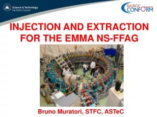
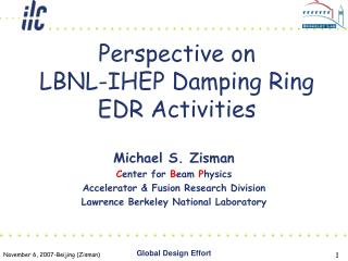
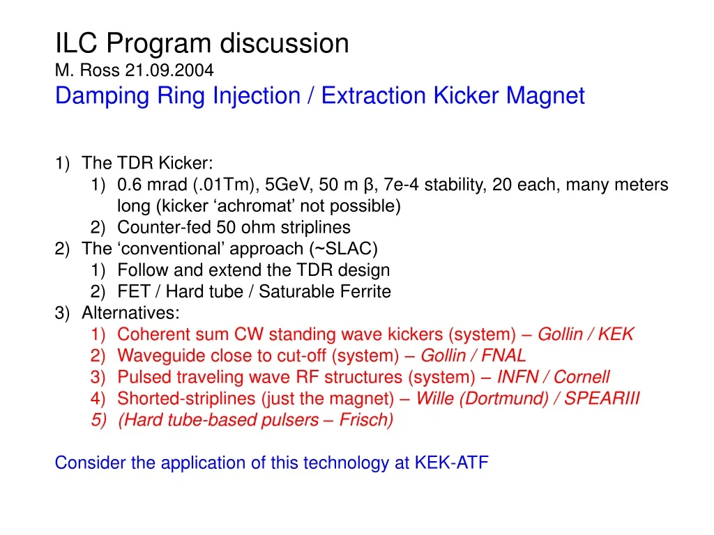
ILC Program discussion M. Ross 21.09.2004 Damping Ring Injection / Extraction Kicker Magnet The TDR Kicker: 0.6 mrad (.01Tm), 5GeV, 50 m β , 7e-4 stability, 20 each, many meters long (kicker ‘achromat’ not possible) Counter-fed 50 ohm striplines The ‘conventional’ approach (~SLAC)

E N D
ILC Program discussion • M. Ross 21.09.2004 • Damping Ring Injection / Extraction Kicker Magnet • The TDR Kicker: • 0.6 mrad (.01Tm), 5GeV, 50 m β, 7e-4 stability, 20 each, many meters long (kicker ‘achromat’ not possible) • Counter-fed 50 ohm striplines • The ‘conventional’ approach (~SLAC) • Follow and extend the TDR design • FET / Hard tube / Saturable Ferrite • Alternatives: • Coherent sum CW standing wave kickers (system) – Gollin / KEK • Waveguide close to cut-off (system) – Gollin / FNAL • Pulsed traveling wave RF structures (system) – INFN / Cornell • Shorted-striplines (just the magnet) – Wille (Dortmund) / SPEARIII • (Hard tube-based pulsers – Frisch) • Consider the application of this technology at KEK-ATF
Counter-fed Stripline (power fed parallel to beam direction gives no kick unless v_g is low) Rise time depends on travelling wave kicker fill time DESY Kicker RD Rummler / Shiltsev / BINP
DESY Kicker RD ITRP Poster (Obier)
(read µ) DESY Kicker RD – 2 stripline magnets built Ongoing RD for XFEL switchyard
ATF Kicker development. (2 programs) • Program 1 – Conventional pulse technology extremely fast kicker: • Extract ~ 20 bunches spaced by 330 ns; to be used for testing ILC instrumentation in the ATF extraction line • Replace existing extraction kicker for test • 25mm aperture, 20KV, 1.3m kicker is enough to extract (3mrad at 1.3GeV) • (500A, 10MW peak) • Six 200 mm long stripline pairs - 12 pulsers ($/¥) • Conventional solid state / planar triode pulser with many counter-fed striplines • Roughly 2x harder than ILC • Uses saturable ferrite ‘shock-line’ technology • Program 2 – long pulse kicker for fast extraction – based on epoxy magnet technology (SLAC DR, ATF injection)
ATF extraction 1.5 m Existing ATF kicker parameters
Work underway at SLAC / LLNL / BN: FET pulsers Shock-lines (Saturable ferrites) Shorted kicker
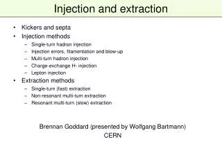
Injection/extraction from trailing edge of a train (J. Rogers) New Ideas – alternative approacnes • Advantages: • Bunches are always extracted and injected at the end of a bunch train, so the injection/extraction kickers need only have a fast rise time. The damping ring can be much smaller than the dogbone design. • Positron bunch production rate is greatly reduced, allowing use of a conventional positron source. • Disadvantage: • An additional small ring is required.
Injection/extraction from trailing edge of a train (J. Rogers) New Ideas – alternative approacnes • Two rings (one large, one small) share a common RF section. • As damped bunches are extracted from the large ring to the bunch compressor and main linacs, bunches are injected into the small ring, avoiding RF transients. • When all of the damped bunches are extracted from the large ring, the small ring is full. A transfer kicker located in the common straight section moves all of the bunches in the small ring as a train to the large ring. This requires a gap before the stored train, which does not appear in the train extracted to the main linac.
circumference of large ring circumference of small ring damping in large ring extraction from large ring injection to small ring transfer from small to large ring extraction to bunch compressor & linac time refill large ring Injection/extraction from trailing edge of a train (J. Rogers) New Ideas – alternative approacnes Simplified timing example: 3 trains of 3 bunches
New Ideas – alternative approacnes George Gollin, University of Illinois
INFN Frascati (Alesino…) New Ideas – alternative approacnes Adaptation of the CLIC compression technology
A New Injection/Extraction Section New Ideas – alternative approacnes • At the injection/extraction point, RF deflectors separate bunches into three separate lines • Two lines have the bunch spacing required by the kicker • Lines are recombined approximately 200 m later • We have worked out timing issues • The right bunch must be in the right line at the right time Injection/Extraction Richard Helms Cornell University Victoria Linear Collider Conference 29 July 2004
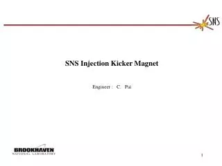
NLC - The Next Linear Collider Project Dortmund Kicker Keith Jobe May, 1999 Slide #
NLC - The Next Linear Collider Project NLC Prototype Keith Jobe May, 1999 Slide #
NLC - The Next Linear Collider Project Probable cross-section • the magnet will require a controlled impedance • water cooling is not allowed in the prototype • vacuum considerations have not been formally addressed Keith Jobe May, 1999 Slide #
9/14/04 R. Cassel With an oscillator generate 15Mhz synchronized with beam. Rectify and extract every fifth pulse ~60nsec switch turn on time and ~60 nsec switch turn off time. Rise & fall time of pulse is ~20nsec with 337nsec between pulses.
9/14/04 R. Cassel “Shock Line” SLC kicker ~38kv into 12.5 ohms. Rise time improvement from ~30nsec to ~ 5 nsec rise time
9/14/04 R. Cassel Extracted pulse and Shock line fits into beam
9/14/04 R. Cassel Extraction and Injection pulses with beam. Extraction is a half sine wave with shock line. Injection is a half sine wave pulse minus a half sine shock line extraction type pulse.
Dear Josef, We think we can make it, subject to any difficult specs. which might emerge (eg very low interpulse noise levels). We have built a FET pulser with a 2ns risetime and an equivalent output of 40kV into 50‡ and this did 60kHz [It was actually 20 channels at 10kV but we can combine outputs to make a large voltage and have taken this approach to 48kV on avalanche units). We have also made other FET pulsers which do multi-MHz bursts. Ionisation is sometimes a bit of an issue with high voltages and high repetition rates. At low rates the ionisation all recombines before the next pulse. As soon as the rate is above around 15kHz the ionisation is still around from the previous shot. It will be quite big (something like a 6 foot high 19" rack) and a very rough first guess is approx $350k for the first one. This is based upon 500 amps into a 50 ohm load. Into a 100 ohm load would require twice the power and a somewhat bigger device. Tony Dymoke-Bradshaw (Director)Kentech Instruments Ltd. http://www.kentech.co.uk/Unit 9, Hall Farm Workshops, South Moreton, Didcot, Oxon, OX11 9AG, U.K.
Kicker issues • Pulser / power source • Stability • Rise time/fall time • Repetition rate (3MHz or 1.6MHz) • ‘achromat’ + feedback/feedforward/active cancellation schemes • Timing rms / voltage rms • Magnet • Beam Impedance • Field flatness • Match • Optics • Ring operational schemes • e+ • Auxiliary (pre?) ring