Download
1 / 37
380 likes | 564 Views
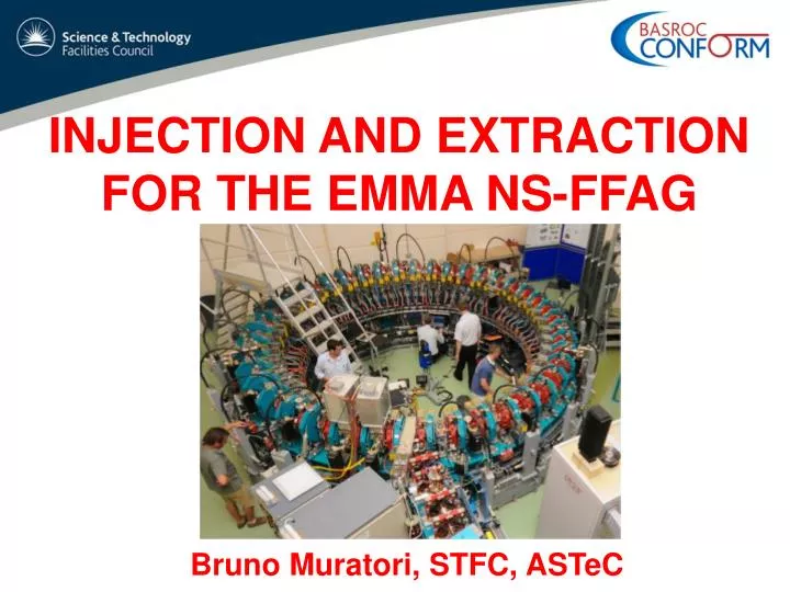
INJECTION AND EXTRACTION FOR THE EMMA NS-FFAG. Bruno Muratori, STFC, ASTeC. Contents. Introduction What are ns-FFAGs? and Why EMMA? The international collaboration EMMA goals and requirements Layout and Lattice Injection & Extraction Beam Commissioning Next Steps Summary.

E N D
INJECTION AND EXTRACTION FOR THE EMMA NS-FFAG Bruno Muratori, STFC, ASTeC
Contents • Introduction • What are ns-FFAGs? and Why EMMA? • The international collaboration • EMMA goals and requirements • Layout and Lattice • Injection & Extraction • Beam Commissioning • Next Steps • Summary
Project Overview BASROC(The British Accelerator Science and Radiation Oncology Consortium, BASROC) • CONFORM project ( COnstruction of a Non-scaling FFAG for Oncology, Research, and Medicine ) • 4 year project April 2007 – March 2011 • 3 parts to the project • EMMA design and construction~ £6.5m (~$9M) Electron Model for Many Applications (EMMA) • PAMELA design study • Applications study
EMMA International Collaboration • EMMA design is an international effort and we recognise and appreciate the active collaboration from: • Brookhaven National Laboratory • Cockcroft Institute UK • Fermi National Accelerator Laboratory • John Adams Institute UK • LPSC, Grenoble • Science & Technology Facilities Council UK • TRIUMF • ………..
EMMA Goals Graphs courtesy of Scott Berg BNL
Understanding the NS-FFAG beam dynamics as function of lattice tuning & RF parameters Lattice Configurations Tune plane • Example: retune lattice to vary resonances crossed during acceleration Time of Flight vs Energy • Example: retune lattice to vary longitudinal Time of Flight curve, range and minimum Graphs courtesy of Scott Berg BNL
Accelerator Requirements • Injection & extraction at all energies, 10 - 20 MeV • Fixed energy operation to map closed orbits and tunes vs momentum • Many lattice configurations • Vary ratio of dipole to quadrupole fields • Vary frequency, amplitude and phase of RF cavities • Map longitudinal and transverse acceptances with probe beam EMMA to be heavily instrumented with beam diagnostics
ALICE Accelerators and Lasers In Combined Experiments Parameter Value Nominal Gun Energy 350 keV Injector Energy 8.35 MeV Max. Energy 35 MeV Linac RF Frequency 1.3 GHz Max Bunch Charge 80 pC Emittance 5-15 mm-mrad EMMA
EMMA Parameters & Layout Diagnostics Beamline Injection Line
EMMA Ring Cell 65 mm Field Clamps 55 mm D D F Low Energy Beam • 42 identical doublets Cavity Beam stay clear aperture High Energy Beam 110 mm Magnet Centre-lines 210 mm Independent slides
EMMA Cell FQUAD Cavity DQUAD Ion Pump Ion Pump Ion Pump Beam direction Girder
A 6 Cell Girder Assembly F Magnet Location for diagnostics Cavity D Magnet Ion Pump Girder Beam direction
Injection line Dogleg to extract beam from ALICE Tomography (dual purpose) Dispersive section to match to EMMA ring with 6 parameters but can be done with 11 variables & maybe more if needed
Injection line • Different energies means different RF focusing & Twiss • Minimise energy spread (done & < 0.05 % at 15 MeV) • Done by straightening the bunch with ALICE linac off-crest • Yet more difference in RF focusing seen • Tomography provides fixed point when matched correctly • Need only keep first screen after that & can further vary quadrupoles to match into EMMA ring • Beam not perfectly centred in injection linebut can achieve good injection nonetheless
Injection & Extraction • Large angle for injection (65°) and extraction (70°) very challenging !! • Injection/Extraction scheme required for all energies (10 – 20 MeV) • Many lattices and many configurations of each lattice required • Very limited space between quadrupole clamp plates for the septum and kickers construction Extensive 3D magnet modelling conducted to minimise the effect of stray septum fields on circulating beam Injection Septum 65° Kicker Kicker
Injection Region Injection Septum 65° Kicker Kicker
Injection Septum Kicker Kicker Septum Power supply
Septum Design Translation Rotation Septum out of vacuum chamber • Inject/Extracts from 10-20 MeV • For all lattice configurations Section view of septum in vacuum chamber
Injection septum • Concept • 3D field map • BPM data analysis • Magnetic measurements Δβmin<0.02 deg. leff=90.865 mm leff=90.865 mm
Kicker Magnet, Fast Switching Kicker Magnet Power Supply parameters With compact design and require: • Fast rise / fall times 35 nS • Rapid changes in current 50kA/S • Constraints on pre and post pulses Prototype R&D led to a contract with APP for production units
Kickers • Concept • Field quality • In-situ field probe • Before installation Max. strength 0.007 Tm Effective length 130 mm Field variation 1.5% Fall time 58 ns Timing jitter 1.7 ns Amplitude stability 4%.
Measured Current Pulsesfrom Kicker Magnet ~55.5 ns = 1 revolution period
Kicker ringing • Only solutionis to have multi-turn injection (~ 2) • Final kicker strength required is ~ the same • Ideal case without ringing • Can have few % ringing • Cannot have 10 %
Kicker ringing Minimise orbit excursions essential Two turn injection feasible over entire EMMA range of energies Ideal excursions: - 8 to 12 mm Two-turn exc.: ~ -15 to 15 mm
Many thanks for the efforts of all the team. 4 Sector Commissioning screen screen
Complete Ring Second Turn First Turn 16th Aug 2010
Optimisation of injection Kicker Septum Kicker • Angle at end of SEPT determined from BPM offsets with quads OFF Use code to determine kicker strengths close to pragmatic strengths Orbit kinks between cells are due to rotation of coordinate system
Time of Flight Revolution time @ equiv 18.5 MeV/c, equivalent momentum = 55.3+/-0.1 ns Variable ALICE energy fixed EMMA fields Fixed ALICE Energy Variable EMMA fields • Time of flight is determined by path length, not by speed • Use different magnetic strength as easier than retuning ALICE injector • Raw signal of one BPM electrode for time of flight measurement ALICE injector
Betatron oscillation tunes & dispersion • Tunes from fit • Beam position at 7 BPMs • Dispersion from average position At 100% effective momentum (15.5 MeV/c) Horzdisp =82mm Vert. disp. = 3mm Consistent to predicted values Horizontal Vertical
Coasting beam no RF Without rf, beam circulates more than 1000 turns Left and right electrode signal of BPM spaced with 13 ns.
Synchrotron Oscillations Still have problem tuning 19 cavity phases RF buckets around transition momentum still separated Seen RF bucket & synchrotron oscillations inside it Going to adjust each cavity phase separately
Next Steps • Commissioning now • LLRF system fully functional and tested at ALICE & off frequency • Verification of successful acceleration, inside/outside bucket • Characterisation • Tunes and ToF fn of E ~ 1MeV steps • Tune accelerator to match required lattice • “EMMA Experiment” • Acceleration 10 – 20 MeV • Resonance crossing • Detailed bench marking with codes • Scan aperture in phase space (both longitudinally and transversely) • Benchmark measured dynamic aperture with and without acceleration against the simulations ...................
Summary • Design and construction phase of the project is complete • Commissioning of the full ring is underway: • Many 1000s of turns at fixed energy • Time of flight measurements have been measured at various quadrupole settings • The LLRF system is commissioning is at an advanced stage and ready for operating to show evidence of acceleration • Next start detailed characterisation of the accelerator A key aim is to:- Verify this new concept works. Compare results with studies & gain real experience. Apply lessons learnt to new applications!
Acknowledgements All the team • STFC Daresbury & Rutherford Appleton Labs , Cockcroft Institute, John Adams Institute, Imperial College staff • International Collaborators • Commercial Suppliers Funding from UK Basic Technology Programme