Download
1 / 12
140 likes | 148 Views
Appendix H Hardware and Software for VLIW and EPIC.

E N D
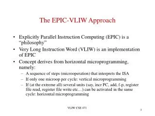
Appendix H Hardware and Software for VLIW and EPIC
Figure H.1 A software-pipelined loop chooses instructions from different loop iterations, thus separating the dependent instructions within one iteration of the original loop. The start-up and finish-up code will correspond to the portions above and below the software-pipelined iteration.
Figure H.2 The execution pattern for (a) a software-pipelined loop and (b) an unrolled loop. The shaded areas are the times when the loop is not running with maximum overlap or parallelism among instructions. This occurs once at the beginning and once at the end for the software-pipelined loop. For the unrolled loop it occurs m/n times if the loop has a total of m iterations and is unrolled n times. Each block represents an unroll of n iterations. Increasing the number of unrollings will reduce the start-up and clean-up overhead. The overhead of one iteration overlaps with the overhead of the next, thereby reducing the impact. The total area under the polygonal region in each case will be the same, since the total number of operations is just the execution rate multiplied by the time.
Figure H.3 A code fragment and the common path shaded with gray. Moving the assignments to B or C requires a more complex analysis than for straight-line code. In this section we focus on scheduling this code segment efficiently without hardware assistance. Predication or conditional instructions, which we discuss in the next section, provide another way to schedule this code.
Figure H.4 This trace is obtained by assuming that the program fragment in Figure H.3 is the inner loop and unwinding it four times, treating the shaded portion in Figure H.3 as the likely path. The trace exits correspond to jumps off the frequent path, and the trace entrances correspond to returns to the trace.
Figure H.5 This superblock results from unrolling the code in Figure H.3 four times and creating a superblock.
Figure H.6 The five execution unit slots in the IA-64 architecture and what instructions types they may hold are shown. A-type instructions, which correspond to integer ALU instructions, may be placed in either an I-unit or M-unit slot. L + X slots are special, as they occupy two instruction slots; L + X instructions are used to encode 64-bit immediates and a few special instructions. L + X instructions are executed either by the I-unit or the B-unit.
Figure H.7 The 24 possible template values (8 possible values are reserved) and the instruction slots and stops for each format. Stops are indicated by heavy lines and may appear within and/or at the end of the bundle. For example, template 9 specifies that the instruction slots are M, M, and I (in that order) and that the only stop is between this bundle and the next. Template 11 has the same type of instruction slots but also includes a stop after the first slot. The L + X format is used when slot 1 is L and slot 2 is X.
Figure H.8 The IA-64 instructions, including bundle bits and stops, for the unrolled version of x[i] = x[i] + s, when unrolled seven times and scheduled (a) to minimize the number of instruction bundles and (b) to minimize the number of cycles (assuming that a hazard stalls an entire bundle). Blank entries indicate unused slots, which are encoded as no-ops. The absence of stops indicates that some bundles could be executed in parallel. Minimizing the number of bundles yields 9 bundles versus the 11 needed to minimize the number of cycles. The scheduled version executes in just over half the number of cycles. Version (a) fills 85% of the instruction slots, while (b) fills 70%. The number of empty slots in the scheduled code and the use of bundles may lead to code sizes that are much larger than other RISC architectures. Note that the branch in the last bundle in both sequences depends on the DADD in the same bundle. In the IA-64 instruction set, this sequence would be coded as a setting of a predication register and a branch that would be predicated on that register. Normally, such dependent operations could not occur in the same bundle, but this case is one of the exceptions mentioned earlier.
Figure H.9 A summary of some of the instruction formats of the IA-64 ISA. The major opcode bits and the guarding predication register specifier add 10 bits to every instruction. The number of formats indicated for each instruction class in the second column (a total of 111) is a strict interpretation: A different use of a field, even of the same size, is considered a different format. The number of formats that actually have different field sizes is one-third to one-half as large. Some instructions have unused bits that are reserved; we have not included those in this table. Immediate bits include the sign bit. The branch instructions include prediction bits, which are used when the predictor does not have a valid prediction. Only one of the many formats for the multimedia instructions is shown in this table.
Figure H.10 The latency of some typical instructions on Itanium 2. The latency is defined as the smallest number of intervening instructions between two dependent instructions. Integer load latency assumes a hit in the first-level cache. FP loads always bypass the primary cache, so the latency is equal to the access time of the second-level cache. There are some minor restrictions for some of the functional units, but these primarily involve the execution of infrequent instructions.
Figure H.11 The performance of four multiple-issue processors for five SPECfp and SPECint benchmarks. The clock rates of the four processors are Itanium 2 at 1.5 GHz, Pentium 4 Extreme Edition at 3.8 GHz, AMD Athlon 64 at 2.8 GHz, and the IBM Power5 at 1.9 GHz.