Download
1 / 98
980 likes | 1.02k Views
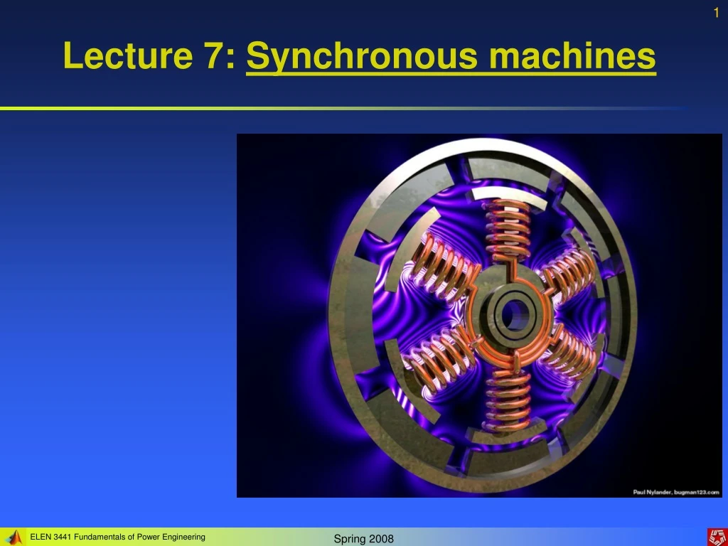
Lecture 7: Synchronous machines. Construction of synchronous machines. Synchronous machines are AC machines that have a field circuit supplied by an external DC source.

E N D
Construction of synchronous machines Synchronous machines are AC machines that have a field circuit supplied by an external DC source. In a synchronous generator, a DC current is applied to the rotor winding producing a rotor magnetic field. The rotor is then turned by external means producing a rotating magnetic field, which induces a 3-phase voltage within the stator winding. In a synchronous motor, a 3-phase set of stator currents produces a rotating magnetic field causing the rotor magnetic field to align with it. The rotor magnetic field is produced by a DC current applied to the rotor winding. Field windings are the windings producing the main magnetic field (rotor windings for synchronous machines); armature windings are the windings where the main voltage is induced (stator windings for synchronous machines).
Construction of synchronous machines The rotor of a synchronous machine is a large electromagnet. The magnetic poles can be either salient (sticking out of rotor surface) or non-salient construction. Non-salient-pole rotor: usually two- and four-pole rotors. Salient-pole rotor: four and more poles. Rotors are made laminated to reduce eddy current losses.
Construction of synchronous machines A synchronous rotor with 8 salient poles Salient pole without field windings – observe laminations Salient pole with field windings
Construction of synchronous machines Two common approaches are used to supply a DC current to the field circuits on the rotating rotor: • Supply the DC power from an external DC source to the rotor by means of slip rings and brushes; • Supply the DC power from a special DC power source mounted directly on the shaft of the machine. Slip rings are metal rings completely encircling the shaft of a machine but insulated from it. One end of a DC rotor winding is connected to each of the two slip rings on the machine’s shaft. Graphite-like carbon brushes connected to DC terminals ride on each slip ring supplying DC voltage to field windings regardless the position or speed of the rotor.
Construction of synchronous machines Slip rings Brush
Construction of synchronous machines Slip rings and brushes have certain disadvantages: increased friction and wear (therefore, needed maintenance), brush voltage drop can introduce significant power losses. Still this approach is used in most small synchronous machines. On large generators and motors, brushless exciters are used. A brushless exciter is a small AC generator whose field circuits are mounted on the stator and armature circuits are mounted on the rotor shaft. The exciter generator’s 3-phase output is rectified to DC by a 3-phase rectifier (mounted on the shaft) and fed into the main DC field circuit. It is possible to adjust the field current on the main machine by controlling the small DC field current of the exciter generator (located on the stator). Since no mechanical contact occurs between the rotor and the stator, exciters of this type require much less maintenance.
Construction of synchronous machines A brushless exciter: a low 3-phase current is rectified and used to supply the field circuit of the exciter (located on the stator). The output of the exciter’s armature circuit (on the rotor) is rectified and used as the field current of the main machine.
Construction of synchronous machines To make the excitation of a generator completely independent of any external power source, a small pilot exciter is often added to the circuit. The pilot exciter is an AC generator with a permanent magnet mounted on the rotor shaft and a 3-phase winding on the stator producing the power for the field circuit of the exciter.
Construction of synchronous machines A rotor of large synchronous machine with a brushless exciter mounted on the same shaft. Many synchronous generators having brushless exciters also include slip rings and brushes to provide emergency source of the field DC current.
Construction of synchronous machines A large synchronous machine with the exciter and salient poles.
Rotation speed of synchronous generator By the definition, synchronous generators produce electricity whose frequency is synchronized with the mechanical rotational speed. (7.11.1) Where fe is the electrical frequency, Hz; nm is mechanical speed of magnetic field (rotor speed for synchronous machine), rpm; P is the number of poles. Steam turbines are most efficient when rotating at high speed; therefore, to generate 60 Hz, they are usually rotating at 3600 rpm and turn 2-pole generators. Water turbines are most efficient when rotating at low speeds (200-300 rpm); therefore, they usually turn generators with many poles.
Internal generated voltage of a synchronous generator The magnitude of internal generated voltage induced in a given stator is where K is a constant representing the construction of the machine, is flux in it and is its rotation speed. Since flux in the machine depends on the field current through it, the internal generated voltage is a function of the rotor field current. Magnetization curve (open-circuit characteristic) of a synchronous machine
Equivalent circuit of a synchronous generator • The internally generated voltage in a single phase of a synchronous machine EA is not usually the voltage appearing at its terminals. It equals to the output voltage V only when there is no armature current in the machine. The reasons that the armature voltage EA is not equal to the output voltage V are: • Distortion of the air-gap magnetic field caused by the current flowing in the stator (armature reaction); • Self-inductance of the armature coils; • Resistance of the armature coils; • Effect of salient-pole rotor shapes.
Equivalent circuit of a synchronous generator Armature reaction (the largest effect): When the rotor of a synchronous generator is spinning, a voltage EA is induced in its stator. When a load is connected, a current starts flowing creating a magnetic field in machine’s stator. This stator magnetic field BS adds to the rotor (main) magnetic field BR affecting the total magnetic field and, therefore, the phase voltage. Lagging load
Equivalent circuit of a synchronous generator Assuming that the generator is connected to a lagging load, the load current IA will create a stator magnetic field BS, which will produce the armature reaction voltage Estat. Therefore, the phase voltage will be (7.16.1) The net magnetic flux will be (7.16.2) Rotor field Stator field Note that the directions of the net magnetic flux and the phase voltage are the same.
Equivalent circuit of a synchronous generator Assuming that the load reactance is X, the armature reaction voltage is (7.17.1) The phase voltage is then (7.17.2) Armature reactance can be modeled by the following circuit… However, in addition to armature reactance effect, the stator coil has a self-inductance LA (XA is the corresponding reactance) and the stator has resistance RA. The phase voltage is thus (7.17.3)
Equivalent circuit of a synchronous generator Often, armature reactance and self-inductance are combined into the synchronous reactance of the machine: (7.18.1) Therefore, the phase voltage is (7.18.2) The equivalent circuit of a 3-phase synchronous generator is shown. The adjustable resistor Radj controls the field current and, therefore, the rotor magnetic field.
Equivalent circuit of a synchronous generator A synchronous generator can be Y- or -connected: The terminal voltage will be (7.19.1) (7.19.2)
Equivalent circuit of a synchronous generator Note: the discussion above assumed a balanced load on the generator! Since – for balanced loads – the three phases of a synchronous generator are identical except for phase angles, per-phase equivalent circuits are often used.
Phasor diagram of a synchronous generator Since the voltages in a synchronous generator are AC voltages, they are usually expressed as phasors. A vector plot of voltages and currents within one phase is called a phasor diagram. A phasor diagram of a synchronous generator with a unity power factor (resistive load) Lagging power factor (inductive load): a larger than for leading PF internal generated voltage EA is needed to form the same phase voltage. Leading power factor (capacitive load). For a given field current and magnitude of load current, the terminal voltage is lower for lagging loads and higher for leading loads.
Power and torque in synchronous generators A synchronous generator needs to be connected to a prime mover whose speed is reasonably constant (to ensure constant frequency of the generated voltage) for various loads. The applied mechanical power (7.22.1) is partially converted to electricity (7.22.2) Where is the angle between EA and IA. The power-flow diagram of a synchronous generator.
Power and torque in synchronous generators The real output power of the synchronous generator is (7.23.1) The reactive output power of the synchronous generator is (7.23.2) Recall that the power factor angle is the angle between V and IA and not the angle between VT and IL. In real synchronous machines of any size, the armature resistance RA << XSand, therefore, the armature resistance can be ignored. Thus, a simplified phasor diagram indicates that (7.23.3)
Power and torque in synchronous generators Then the real output power of the synchronous generator can be approximated as (7.24.1) We observe that electrical losses are assumed to be zero since the resistance is neglected. Therefore: (7.24.2) Here is the torque angle of the machine– the angle between V and EA. The maximum power can be supplied by the generator when = 900: (7.24.3)
Power and torque in synchronous generators The maximum power specified by (7.24.3) is called the static stability limit of the generator. Normally, real generators do not approach this limit: full-load torque angles are usually between 150 and 200. The induced torque is (7.25.1) Notice that the torque angle is also the angle between the rotor magnetic field BR and the net magnetic field Bnet. Alternatively, the induced torque is (7.25.2)
Measuring parameters of synchronous generator model • The three quantities must be determined in order to describe the generator model: • The relationship between field current and flux (and therefore between the field current IF and the internal generated voltage EA); • The synchronous reactance; • The armature resistance. We conduct first the open-circuit test on the synchronous generator: the generator is rotated at the rated speed, all the terminals are disconnected from loads, the field current is set to zero first. Next, the field current is increased in steps and the phase voltage (whish is equal to the internal generated voltage EA since the armature current is zero) is measured. Therefore, it is possible to plot the dependence of the internal generated voltage on the field current – the open-circuit characteristic (OCC) of the generator.
Measuring parameters of synchronous generator model Since the unsaturated core of the machine has a reluctance thousands times lower than the reluctance of the air-gap, the resulting flux increases linearly first. When the saturation is reached, the core reluctance greatly increases causing the flux to increase much slower with the increase of the mmf. We conduct next the short-circuit test on the synchronous generator: the generator is rotated at the rated speed, all the terminals are short-circuited through ammeters, the field current is set to zero first. Next, the field current is increased in steps and the armature current IA is measured as the field current is increased. The plot of armature current (or line current) vs. the field current is the short-circuit characteristic (SCC) of the generator.
Measuring parameters of synchronous generator model The SCC is a straight line since, for the short-circuited terminals, the magnitude of the armature current is (7.28.1) The equivalent generator’s circuit during SC The resulting phasor diagram The magnetic fields during short-circuit test Since BS almost cancels BR, the net field Bnet is very small.
Measuring parameters of synchronous generator model • An approximate method to determine the synchronous reactance XS at a given field current: • Get the internal generated voltage EA from the OCC at that field current. • Get the short-circuit current IA,SC at that field current from the SCC. • Find XS from (7.29.1) Since the internal machine impedance is (7.29.2)
Measuring parameters of synchronous generator model A drawback of this method is that the internal generated voltage EA is measured during the OCC, where the machine can be saturated for large field currents, while the armature current is measured in SCC, where the core is unsaturated. Therefore, this approach is accurate for unsaturated cores only. The approximate value of synchronous reactance varies with the degree of saturation of the OCC. Therefore, the value of the synchronous reactance for a given problem should be estimated at the approximate load of the machine. The winding’s resistance can be approximated by applying a DC voltage to a stationary machine’s winding and measuring the current. However, AC resistance is slightly larger than DC resistance (skin effect).
Measuring parameters of synchronous generator model: Ex • Example 7.1: A 200 kVA, 480 V, 50 Hz, Y-connected synchronous generator with a rated field current of 5 A was tested and the following data were obtained: • VT,OC = 540 V at the rated IF. • IL,SC = 300 A at the rated IF. • When a DC voltage of 10 V was applied to two of the terminals, a current of 25 A was measured. • Find the generator’s model at the rated conditions (i.e., the armature resistance and the approximate synchronous reactance). Since the generator is Y-connected, a DC voltage was applied between its two phases. Therefore:
Measuring parameters of synchronous generator model: Ex The internal generated voltage at the rated field current is The synchronous reactance at the rated field current is precisely We observe that if XS was estimated via the approximate formula, the result would be: Which is close to the previous result. The error ignoring RA is much smaller than the error due to core saturation. The equivalent circuit
The Synchronous generator operating alone The behavior of a synchronous generator varies greatly under load depending on the power factor of the load and on whether the generator is working alone or in parallel with other synchronous generators. Although most of the synchronous generators in the world operate as parts of large power systems, we start our discussion assuming that the synchronous generator works alone. Unless otherwise stated, the speed of the generator is assumed constant.
The Synchronous generator operating alone Effects of load changes A increase in the load is an increase in the real and/or reactive power drawn from the generator. Since the field resistor is unaffected, the field current is constant and, therefore, the flux is constant too. Since the speed is assumed as constant, the magnitude of the internal generated voltage is constant also. Assuming the same power factor of the load, change in load will change the magnitude of the armature current IA. However, the angle will be the same (for a constant PF). Thus, the armature reaction voltage jXSIA will be larger for the increased load. Since the magnitude of the internal generated voltage is constant (7.34.1) Armature reaction voltage vector will “move parallel” to its initial position.
The Synchronous generator operating alone Increase load effect on generators with Leading PF Lagging PF Unity PF
The Synchronous generator operating alone Generally, when a load on a synchronous generator is added, the following changes can be observed: • For lagging (inductive) loads, the phase (and terminal) voltage decreases significantly. • For unity power factor (purely resistive) loads, the phase (and terminal) voltage decreases slightly. • For leading (capacitive) loads, the phase (and terminal) voltage rises. Effects of adding loads can be described by the voltage regulation: (7.36.1) Where Vnl is the no-load voltage of the generator and Vfl is its full-load voltage.
The Synchronous generator operating alone A synchronous generator operating at a lagging power factor has a fairly largepositive voltage regulation. A synchronous generator operating at a unity power factor has a smallpositive voltage regulation. A synchronous generator operating at a leading power factor often has a negative voltage regulation. Normally, a constant terminal voltage supplied by a generator is desired. Since the armature reactance cannot be controlled, an obvious approach to adjust the terminal voltage is by controlling the internal generated voltage EA = K. This may be done by changing flux in the machine while varying the value of the field resistance RF, which is summarized: • Decreasing the field resistance increases the field current in the generator. • An increase in the field current increases the flux in the machine. • An increased flux leads to the increase in the internal generated voltage. • An increase in the internal generated voltage increases the terminal voltage of the generator. Therefore, the terminal voltage of the generator can be changed by adjusting the field resistance.
The Synchronous generator operating alone: Example Example 7.2: A 480 V, 60 Hz, Y-connected six-pole synchronous generator has a per-phase synchronous reactance of 1.0 . Its full-load armature current is 60 A at 0.8 PF lagging. Its friction and windage losses are 1.5 kW and core losses are 1.0 kW at 60 Hz at full load. Assume that the armature resistance (and, therefore, the I2R losses) can be ignored. The field current has been adjusted such that the no-load terminal voltage is 480 V. • What is the speed of rotation of this generator? • What is the terminal voltage of the generator if • It is loaded with the rated current at 0.8 PF lagging; • It is loaded with the rated current at 1.0 PF; • It is loaded with the rated current at 0.8 PF leading. • c. What is the efficiency of this generator (ignoring the unknown electrical losses) when it is operating at the rated current and 0.8 PF lagging? • d. How much shaft torque must be applied by the prime mover at the full load? • how large is the induced countertorque? • e. What is the voltage regulation of this generator at 0.8 PF lagging? at 1.0 PF? at 0.8 PF leading?
The Synchronous generator operating alone: Example Since the generator is Y-connected, its phase voltage is At no load, the armature current IA = 0 and the internal generated voltage is EA = 277 V and it is constant since the field current was initially adjusted that way. a. The speed of rotation of a synchronous generator is which is b.1. For the generator at the rated current and the 0.8 PF lagging, the phasor diagram is shown. The phase voltage is at 00, the magnitude of EA is 277 V,
The Synchronous generator operating alone: Example and that Two unknown quantities are the magnitude of V and the angle of EA. From the phasor diagram: Then: Since the generator is Y-connected,
The Synchronous generator operating alone: Example b.2. For the generator at the rated current and the 1.0 PF, the phasor diagram is shown. Then: and b.3. For the generator at the rated current and the 0.8 PF leading, the phasor diagram is shown. Then: and
The Synchronous generator operating alone: Example c. The output power of the generator at 60 A and 0.8 PF lagging is The mechanical input power is given by The efficiency is d. The input torque of the generator is
The Synchronous generator operating alone: Example The induced countertorque of the generator is e. The voltage regulation of the generator is Lagging PF: Unity PF: Lagging PF:
Terminal characteristics of synchronous generators All generators are driven by a prime mover, such as a steam, gas, water, wind turbines, diesel engines, etc. Regardless the power source, most of prime movers tend to slow down with increasing the load. This decrease in speed is usually nonlinear but governor mechanisms of some type may be included to linearize this dependence. The speed drop (SD) of a prime mover is defined as: (7.44.1) Most prime movers have a speed drop from 2% to 4%. Most governors have a mechanism to adjust the turbine’s no-load speed (set-point adjustment).
Terminal characteristics of synchronous generators A typical speed vs. power plot A typical frequency vs. power plot Since the shaft speed is linked to the electrical frequency as (7.45.1) the power output from the generator is related to its frequency: (7.45.2) Operating frequency of the system Slope of curve, W/Hz
Terminal characteristics of synchronous generators A similar relationship can be derived for the reactive power Q and terminal voltage VT. When adding a lagging load to a synchronous generator, its terminal voltage decreases. When adding a leading load to a synchronous generator, its terminal voltage increases. The plot of terminal voltage vs. reactive power is not necessarily linear. Both the frequency-power and terminal voltage vs. reactive power characteristics are important for parallel operations of generators. • When a generator is operating alone supplying the load: • The real and reactive powers are the amounts demanded by the load. • The governor of the prime mover controls the operating frequency of the system. • The field current controls the terminal voltage of the power system.
Terminal characteristics of synchronous generators: Example Example 7.3: A generator with no-load frequency of 61.0 Hz and a slope sp of 1 MW/Hz is connected to Load 1 consuming 1 MW of real power at 0.8 PF lagging. Load 2 (that is to be connected to the generator) consumes a real power of 0.8 MW at 0.707 PF lagging. • Find the operating frequency of the system before the switch is closed. • Find the operating frequency of the system after the switch is closed. • What action could an operator take to restore the system frequency to 60 Hz after both loads are connected to the generator? The power produced by the generator is Therefore:
Terminal characteristics of synchronous generators: Example a. The frequency of the system with one load is b. The frequency of the system with two loads is c. To restore the system to the proper operating frequency, the operator should increase the governor no-load set point by 0.8 Hz, to 61.8 Hz. This will restore the system frequency of 60 Hz.
Parallel operation of synchronous generators • Most of synchronous generators are operating in parallel with other synchronous generators to supply power to the same power system. Obvious advantages of this arrangement are: • Several generators can supply a bigger load; • A failure of a single generator does not result in a total power loss to the load increasing reliability of the power system; • Individual generators may be removed from the power system for maintenance without shutting down the load; • A single generator not operating at near full load might be quite inefficient. While having several generators in parallel, it is possible to turn off some of them when operating the rest at near full-load condition.
Conditions required for paralleling A diagram shows that Generator 2 (oncoming generator) will be connected in parallel when the switch S1 is closed. However, closing the switch at an arbitrary momentcan severely damage both generators! • If voltages are not exactly the same in both lines (i.e. in a and a’, b and b’ etc.), a very large current will flow when the switch is closed. Therefore, to avoid this, voltages coming from both generators must be exactly the same. Therefore, the following conditions must be met: • The rms line voltages of the two generators must be equal. • The two generators must have the same phase sequence. • The phase angles of two a phases must be equal. • The frequency of the oncoming generator must be slightly higher than the frequency of the running system.